
Reactive negative sequence current mixed synergic control device and method for electrified railway
A technology for electrified railways and collaborative control, applied in harmonic reduction devices, reactive power adjustment/elimination/compensation, flexible AC transmission systems, etc., can solve problems such as reduced reliability, high noise, and poor dynamic response, and achieve increased Effects of device stability, increased response speed, and reduced compensation capacity
Patent Information
- Authority / Receiving Office
- CN · China
- Patent Type
- Patents(China)
- Current Assignee / Owner
- Publication Date
- 2015-04-15
Smart Images
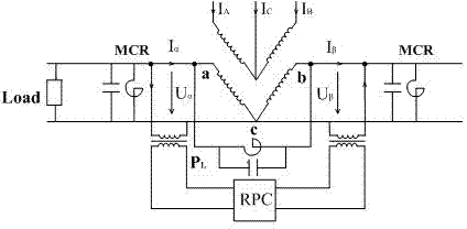
Figure 1 
Figure 2 
Figure 3
Abstract
Description
technical field
[0001] The invention relates to a reactive power negative sequence current coordinated control device and a method thereof for an electrified railway, in particular to a reactive power negative sequence current hybrid coordinated control device and a method for an electrified railway. Background technique
[0002] The traction load of electrified railway is an important source of electric energy pollution in the power system, and the power quality of electrified railway has been widely concerned by many scholars and technicians. Compared with other loads, electrified railway traction load has the following prominent features: single-phase independent asymmetry, high negative sequence content; high-power rectified load, low power factor, high harmonic content, mainly containing 3, 5 , 7th harmonic; random fluctuation, the power of the locomotive running on the railway is random, and the voltage fluctuates greatly. The high-speed railway is fast and powerful, ...
Examples
Embodiment Construction
[0042] The technical solutions of the present invention will be further specifically described below through the embodiments and in conjunction with the accompanying drawings.
[0043] First, introduce the basic principle of the present invention. The present invention has two compensation methods, namely full compensation and optimized compensation:
[0044] (1) The working principle of full compensation: the compensation structure diagram is as follows figure 1 As shown, MCR+FC devices are connected in parallel on the two load sides, ie ca and bc sides, to compensate reactive power and negative sequence, and at the same time, small-capacity RPC devices are connected in parallel through two step-down transformers to absorb and emit active power and reactive power. Because the power factor of the high-speed railway is relatively high, the reactive power compensation is completed by the compensation device on both sides. That is to say, RPC mainly works in reactive power and n...