
A manufacturing method for identification and decoration member of clock surface
A decorative component and literal technology, which is applied in the field of marking and decoration on the surface of watches and clocks, and can solve the problems of high cost, lack of layering, and easy falling off.
Patent Information
- Authority / Receiving Office
- CN · China
- Patent Type
- Applications(China)
- Current Assignee / Owner
- Publication Date
- 2013-01-02
- Estimated Expiration
- Not applicable · inactive patent
Smart Images
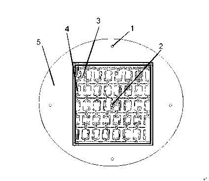
Figure 1 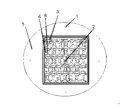
Figure 2 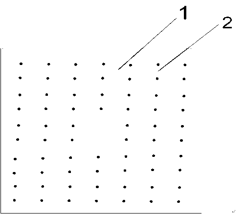
Figure 3
Abstract
Description
technical field
[0001] The invention belongs to the field of watch manufacturing, in particular to a mark and decoration on the surface of a watch. Background technique
[0002] With the continuous development and improvement of the watch industry, consumers have higher and higher requirements for watches. As far as the surface technology of the watch is concerned, it is the most direct factor that determines the appearance of the watch. At present, most of the surface CNC processing, printing or letter pasting processes are used in the market. This process is expensive or easy to fall off, and does not have a sense of hierarchy defect. Contents of the invention
[0003] The purpose of the present invention is to realize the surface positioning of the patented product, realize the sense of hierarchy, reduce the production and processing cost of clocks and watches, and increase the market value.
[0004] In order to achieve the above object, the present invention ad...
Examples
Embodiment Construction
[0014] Further description will be given below in conjunction with the accompanying drawings and specific embodiments, but the scope of protection of the present invention is not limited thereto.
[0015] figure 1 As shown, it is a picture of a semi-finished product that has been processed. The 1 and 2 shown in the figure are all positioning holes, and the number of positioning holes is plural on the base material. Shown in figure 3 is the position that needs to be reserved after twice CNC processing on the base material, namely the product produced by the present invention. It will be detached from the base material 5 when the reverse side is processed for the second time. The position of 4 in the figure is the required dispensing position, and its range is the range marked in the inner black box.
[0016] figure 2 As shown, it is a patented product that has been processed on both sides, and the leftovers have not been removed. 6 is the positioning hole (feet) on the bac...