
Bend angle adjustment testing frame for field strength probe
A technology of angle adjustment and test frame, which is applied in the direction of the measuring device shell, etc., to achieve the effect of easy portability, improved test accuracy and efficiency, and small impact
Patent Information
- Authority / Receiving Office
- CN · China
- Patent Type
- Patents(China)
- Current Assignee / Owner
- Publication Date
- 2015-02-11
- Estimated Expiration
- Not applicable · inactive patent
Smart Images
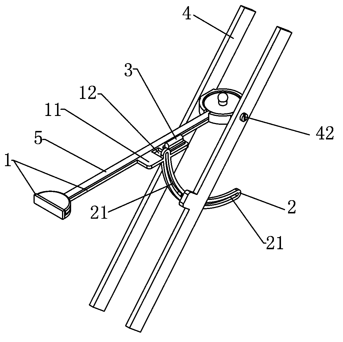
Figure 1 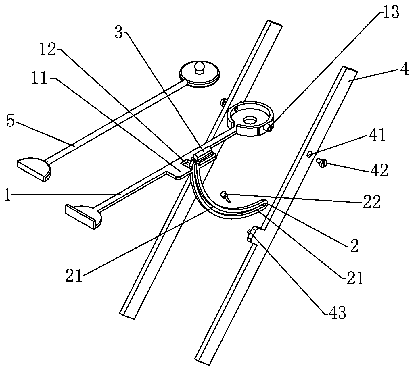
Figure 2
Abstract
Description
technical field
[0001] The invention relates to a test frame for an electromagnetic field probe, in particular to a test frame for adjusting the curved track angle of a field strength probe. Background technique
[0002] At present, the test equipment in the laboratory is basically supported by a tripod. Usually, after the probe is connected to the cable, there will be a certain degree of inclination due to the cable being too heavy. If you want to ensure the attitude of the test probe is level, you must use the tripod. Adjusting the length of the three legs requires multiple people to operate. At the same time, adjusting the legs of the tripod will introduce new test errors, which will bring a certain degree of workload to the probe test. At the same time, it is difficult to guarantee the test accuracy. Contents of the invention
[0003] The technical problem to be solved by the present invention is to provide a test frame for adjusting the angle of the field strength pro...
Examples
Embodiment 1
[0022] see Figure 1-2 As shown, a field strength probe curved track angle adjustment test frame includes a probe bracket 1, a curved track 2, a level 3 and an external test rotatable part 4;
[0023] Described probe holder 1 is provided with protruding platform 11, and level instrument 3 is set on this platform 11; In order to reduce the impact on the electromagnetic field test, it must also have a certain strength as a support frame.); The probe bracket 1 is used to set the probe 5;
[0024] The middle part of described platform 11 is provided with groove 12, and curved rail 2 is fixed in this groove 12;
[0025] The curved track 2 is arc-shaped, and a hollow angle-changing track 21 is provided in the middle;
[0026] One end of the probe holder 1 is provided with a rotating central axis 13 on both sides of the wall, and an external rotating hole 41 is provided on the external test rotatable part 4; the rotating central axis 13 is rotatably arranged in the external rotatin...