
Driving motor for vehicle
A technology for driving motors and vehicles. It is applied in the direction of electrical components, electromechanical devices, and electric components. It can solve the problems of good sealing, affecting the precision of the motor, and troublesome replacement, and achieves the effect of reliable fixing and convenient disassembly and assembly of Hall elements.
Patent Information
- Authority / Receiving Office
- CN · China
- Current Assignee / Owner
- Publication Date
- 2013-08-14
- Estimated Expiration
- Not applicable · inactive patent
Smart Images
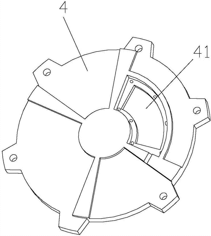
Figure 1 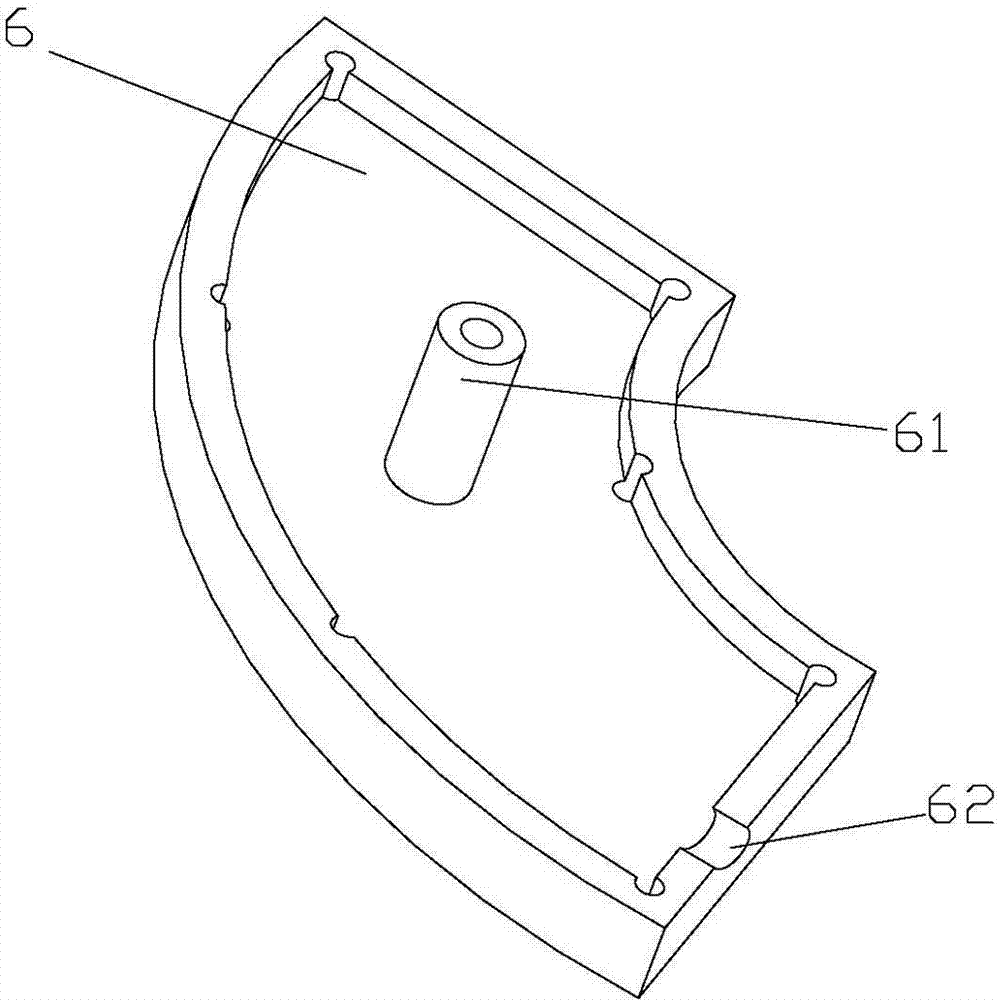
Figure 2 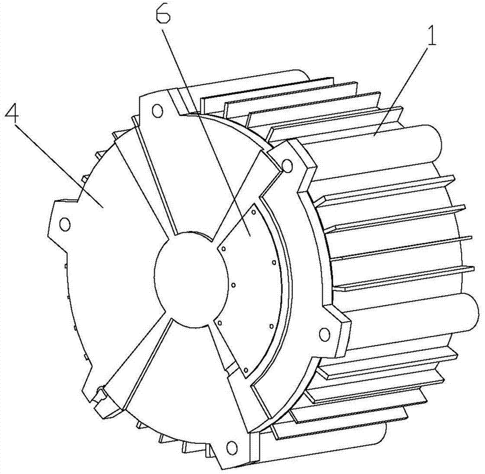
Figure 3
Abstract
Description
technical field
[0001] The invention relates to a motor, in particular to a driving motor of a vehicle. Background technique
[0002] Motors are commonly used equipment in daily industry and life. Among them, the Hall element is an important part of the stability of the motor, and it is also the most vulnerable component. However, the driving motor of a high-power vehicle is generally installed at the bottom of the vehicle, and has a large volume and tightness. Well, when the Hall element is damaged, it is very troublesome to replace it. The driving motor needs to be removed from the vehicle and repaired. After the repair and reassembly, the precision of the motor will inevitably be affected, thereby affecting the normal operation and service life of the motor. . Contents of the invention
[0003] The purpose of the present invention is to provide a driving motor for a vehicle. The Hall element of the driving motor is inserted on the stator core, and an opening is left at...
Examples
Embodiment Construction
[0013] Such as Figure 1-4 As shown, a driving motor for a vehicle includes a housing 1, a stator 2, a rotor 3 and an end cover 4. The stator 2 and the rotor 3 are housed in the housing 1 and arranged coaxially. The Hall element 5, the Hall element 5 is provided with a pin 51, and the rear end of the iron core of the stator 2 corresponding to it is provided with a jack 21, and the Hall element 5 is inserted into the jack 21 through the pin 51 Fixed, there is a gap 41 at the position corresponding to the end cover 4 and the Hall element 5, a sealing cover 6 is provided at the gap 41, and a push rod or a top tube 61 is also provided on the inside of the sealing cover 6, when When the sealing cover 6 is fastened to the sealed notch 41, the ejector rod or the ejector tube 61 can withstand the Hall element 5; a line hole 62 is opened at the edge of the notch 41 and the sealing cover 6 for the control line of the Hall element 5 to pass through .
[0014] The Hall element of the dr...