
A method for eliminating geometric artifacts in cbct and a cbct system using the method
A technology of geometric artifact and coordinate system, applied in the field of CBCT system, can solve the problems of complex calculation, many parameters, low precision, etc., to achieve the effect of simple formula, increase processing speed, and reduce parameters
Patent Information
- Authority / Receiving Office
- CN · China
- Patent Type
- Patents(China)
- Current Assignee / Owner
- Publication Date
- 2017-05-03
Smart Images
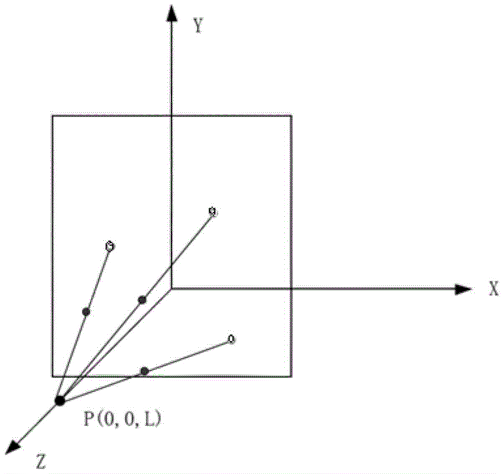
Figure 1 
Figure 2 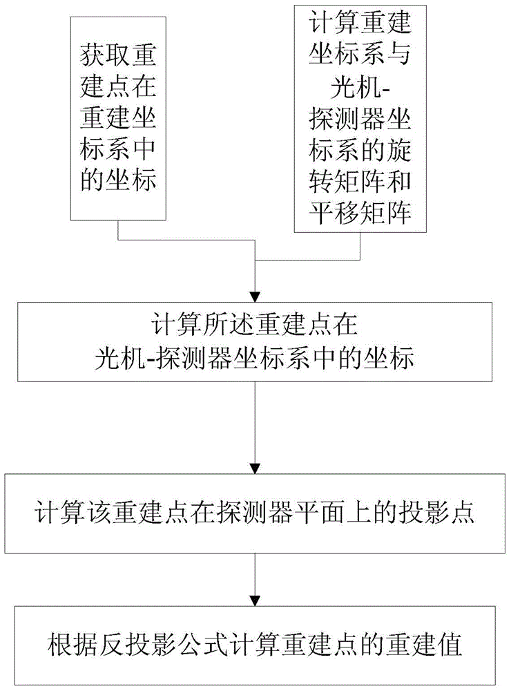
Figure 3
Abstract
Description
technical field
[0001] The invention relates to the field of imaging, in particular to a method for eliminating geometric artifacts in CBCT and a CBCT system using the method. Background technique
[0002] CBCT is the abbreviation of Cone beam CT, that is, cone beam CT, which is a cone beam projection computerized reconstruction tomography imaging device. Then the data obtained in the "intersection" after multiple digital projections around the projection body are reorganized in the computer to obtain a three-dimensional image. CBCT has a high isotropic spatial resolution, and the imaging definition obtained is high.
[0003] Since cone-beam CT (CBCT) can obtain high-precision three-dimensional images of scanned patients, it plays an important role in the diagnosis and treatment of oral diseases and imaging during surgery. In dental CT, most of them use cone-beam CT, which uses flat-panel detectors to detect X-ray attenuation information. Under this design, the X-ray sour...
Examples
Embodiment 1
[0056] First of all, let me introduce the common method of geometric reconstruction in CBCT, that is, the FDK reconstruction method. The last step of the back-projection process is:
[0057]
[0058] In the above formula, f(u) represents the reconstruction value of the reconstruction point u, where u is a 3×1 matrix. is the filtered data, U is the weighting coefficient, in the X-ray source-detector coordinate system (X,Y) represents the projected position of u on the detector plane under angle β.
[0059] as attached figure 1 In , the XYZ coordinate system is the X-ray source-detector coordinate system, where the XOY plane is the plane where the detector is located, and point P is on the Z axis and is the point where the XX-ray source emits rays. The dots are marked points in the phantom, and the dots are the points projected onto the detector plane.
[0060] In order to complete the above back projection process, it is necessary to obtain the projected position (X, Y)...
Embodiment 2
[0109] A CBCT system is provided in this embodiment, the structure is as follows Figure 4 As shown, it is characterized in that it includes:
[0110] The ray source C1 emits ray;
[0111] The detector C2 is arranged opposite to the radiation source, and its relative position to the radiation source is fixed;
[0112] The carrying mechanism is an object stage, which is arranged between the radiation source and the detector, and is used to set the phantom C2 or the object to be measured;
[0113] The phantom C2 is arranged between the ray source C1 and the detector C3, and at least three projection points are formed, and the rays of the ray source are projected onto the detector plane through the projection points;
[0114] The calculation processing unit runs the method for eliminating geometric artifacts in Embodiment 1. First, it receives the scan data of the phantom at different angles, calculates the translation matrix and rotation matrix at different angles, and then ca...