
Electric lifting mechanism
An electric lifting mechanism and electric push rod technology, which is applied to lifting devices, connecting components, mechanical equipment, etc., can solve the problems of inability to adjust the height of the LED screen light box, lack of lifting adjustment devices, and the lifting operation is not stable enough. The overall structure is compact and the appearance is simple
Patent Information
- Authority / Receiving Office
- CN · China
- Patent Type
- Patents(China)
- Current Assignee / Owner
- Publication Date
- 2017-02-22
- Estimated Expiration
- Not applicable · inactive patent
Smart Images
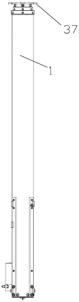
Figure 1 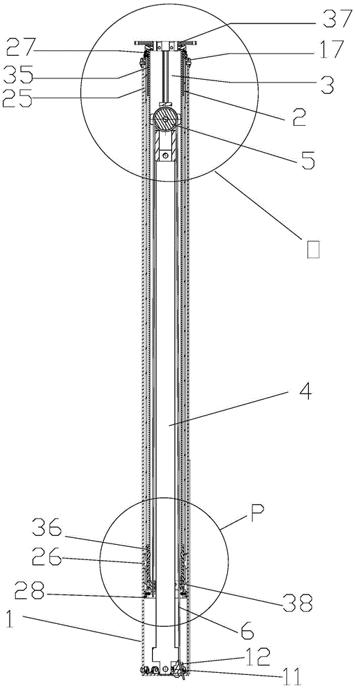
Figure 2 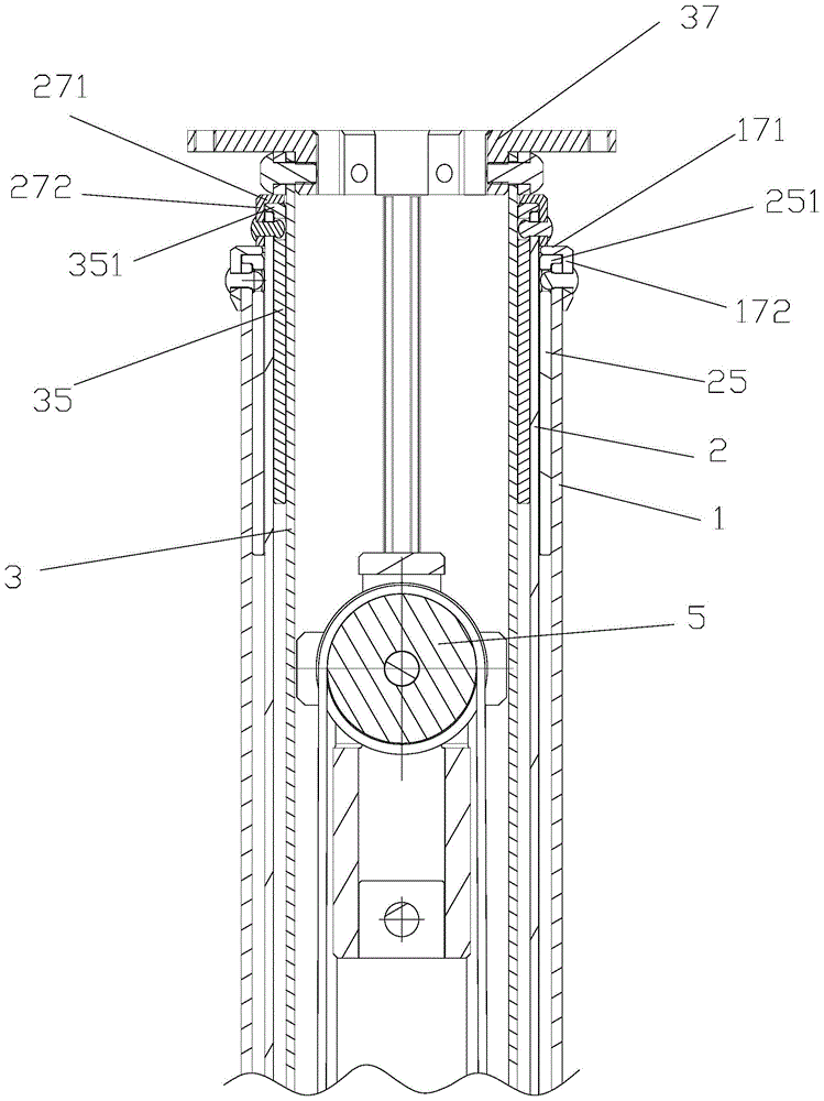
Figure 3
Abstract
Description
technical field
[0001] The invention relates to a lifting mechanism, in particular to an electric lifting mechanism of a light box. Background technique
[0002] At present, most of the LED screen light boxes used in the market cannot be adjusted in height, and lack special lifting adjustment devices. However, some known lifting structures have the disadvantages of complex structure, difficult maintenance, high manufacturing cost, and uneven lifting operation. Contents of the invention
[0003] The technical problem to be solved by the present invention is to provide an electric lifting mechanism with simple structure, stable lifting operation and low manufacturing cost.
[0004] In order to solve the problems of the technologies described above, the technical solution adopted in the present invention is:
[0005] An electric lifting mechanism, including a casing, an electric push rod, a pulley and a steel wire rope wound on the pulley; the casing includes an outer tube,...
Examples
Embodiment Construction
[0016] The present invention will be further described below in conjunction with the accompanying drawings.
[0017] Please refer to Figure 1 to Figure 6 . An electric lifting mechanism according to an embodiment of the present invention includes a bushing, an electric push rod 4 , a pulley 5 and a wire rope 6 wound on the pulley 5 . The sleeve includes an outer tube 1 , a middle tube 2 and an inner tube 3 from outside to inside.
[0018] The bottom of the lumen of the outer tube 1 is provided with an electric push rod fixing part 11 and a wire rope fixing part 12 . The top of the lumen of the outer tube 1 is fixedly provided with an upper bushing 25 of the middle tube. A circle of flanging 251 is provided on the top of the upper bushing 25 of the middle pipe, and the bottom surface of the circle of flanging 251 of the middle pipe upper bush is pressed against the upper end surface of the outer pipe. The upper end of the outer pipe is fixedly provided with an outer pipe u...