
A waste heat boiler flue automatic pressure relief baffle structure
A technology of waste heat boiler and automatic venting, which is applied in the direction of lighting and heating equipment, combustion methods, exhaust gas devices, etc., which can solve the problems of damage, materials not up to the standard specifications, large consumption of manpower and financial resources, etc., and increase the service life , change the structural shape, enhance the effect of service life
Patent Information
- Authority / Receiving Office
- CN · China
- Patent Type
- Patents(China)
- Current Assignee / Owner
- Publication Date
- 2019-02-15
Smart Images
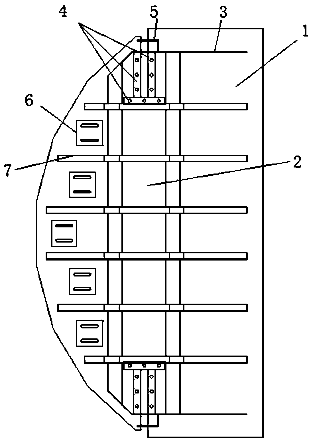
Figure 1 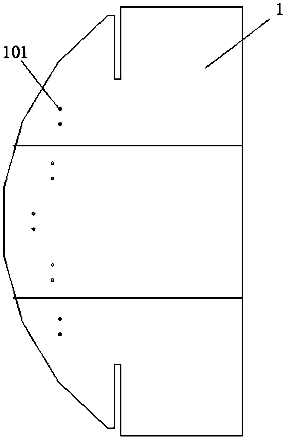
Figure 2 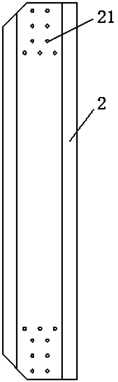
Figure 3
Abstract
Description
technical field
[0001] The invention relates to the technical field of flue baffles, in particular to a waste heat boiler flue automatic pressure relief baffle structure. Background technique
[0002] The flue of the waste heat boiler usually needs to be installed with a baffle, which will not fall into rainwater or dust during use. The baffle will be damaged due to heat and other reasons during use, and the existing flue baffle has a single structure. The materials used cannot meet the standard specifications, and will be damaged after a long time, cannot meet the conditions of use, and cannot achieve the effect of automatic shutdown. In terms of maintenance, it consumes a lot of manpower and financial resources, which also brings difficulties to normal production. Unnecessary trouble, for this reason, we propose a waste heat boiler flue automatic pressure relief baffle structure. Contents of the invention
[0003] The object of the present invention is to provide a wast...
Examples
Embodiment Construction
[0015] The following will clearly and completely describe the technical solutions in the embodiments of the present invention with reference to the accompanying drawings in the embodiments of the present invention. Obviously, the described embodiments are only some, not all, embodiments of the present invention. Based on the embodiments of the present invention, all other embodiments obtained by persons of ordinary skill in the art without making creative efforts belong to the protection scope of the present invention.
[0016] see Figure 1-5 , the present invention provides a technical solution: a waste heat boiler flue automatic pressure relief baffle structure, including a blade 1, the left end of the blade 1 is provided with uniformly distributed connection holes 101, and the left end surface of the blade 1 is fixedly installed There is a center of gravity adjustment plate 6, and the openings at the upper and lower ends of the blade 1 are respectively fixedly connected wi...