
Efficient tapping clamping device
A clamping device, high-efficiency technology, applied in positioning device, tangent device, clamping and other directions, can solve the problems of low tapping precision, low efficiency, inconvenient and stable, etc., and achieve the effect of high tapping precision and high efficiency
Patent Information
- Authority / Receiving Office
- CN · China
- Patent Type
- Applications(China)
- Current Assignee / Owner
- Publication Date
- 2017-06-30
- Estimated Expiration
- Not applicable · inactive patent
Smart Images
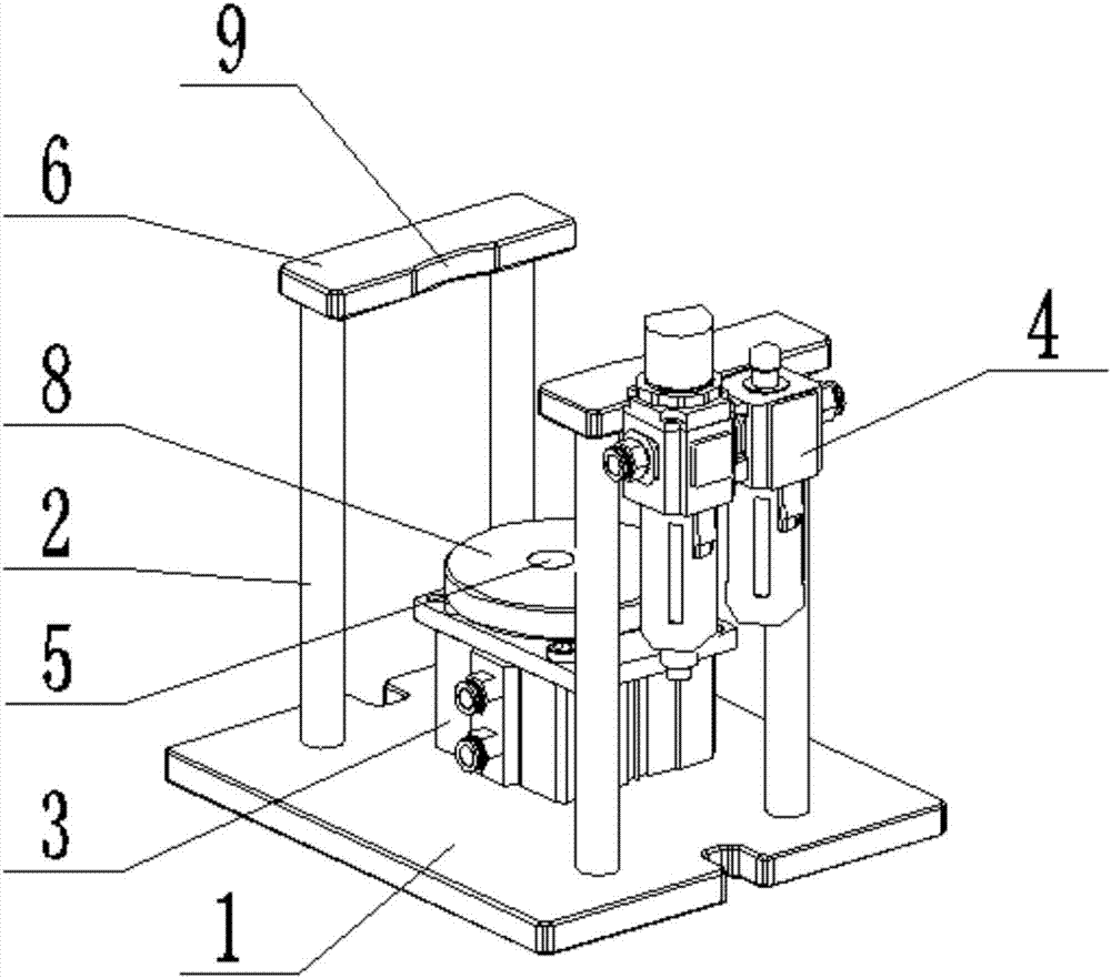
Figure 1 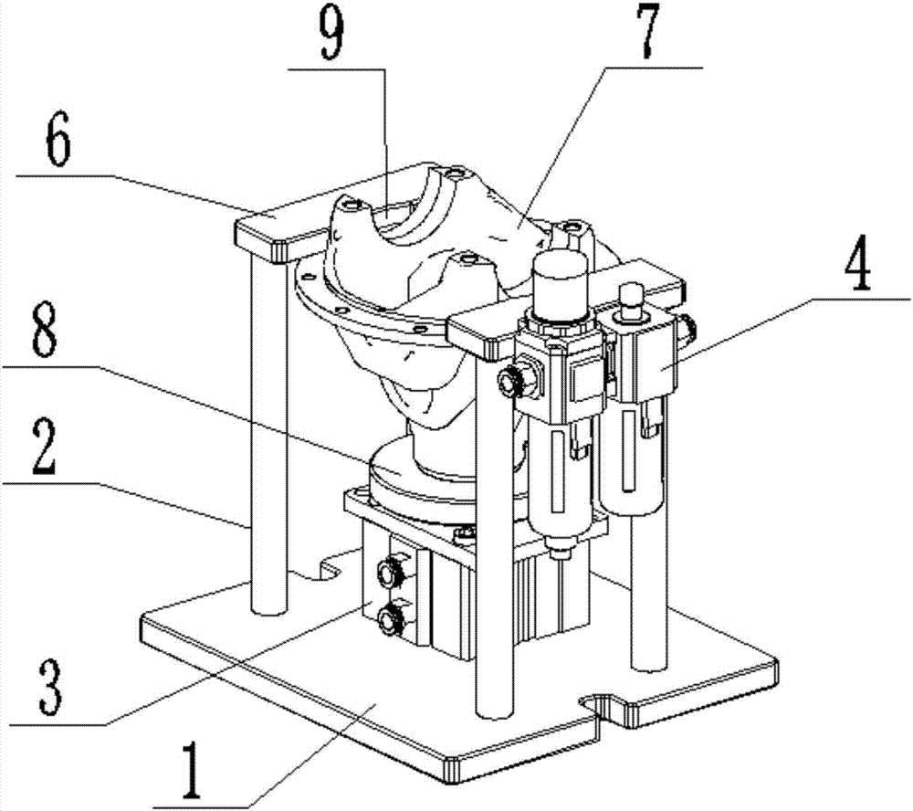
Figure 2
Abstract
Description
technical field
[0001] The invention relates to a high-efficiency tapping and clamping device. Background technique
[0002] In the prior art, tapping irregular workpieces is not convenient for stabilization, and the tapping precision and efficiency are low. Contents of the invention
[0003] The object of the present invention is to provide a high-efficiency tapping and clamping device. The technical problems to be solved are: it is inconvenient to stabilize when tapping irregular workpieces, and the tapping precision and efficiency are low.
[0004] The technical solution of the present invention to solve the above-mentioned technical problems is as follows: a high-efficiency tapping and clamping device includes a base, two support frames, a pneumatic cylinder, an air pressure valve and a pressure relay, and the two support frames are respectively fixed on the base On both sides of the upper end, the upper ends of the two support frames are fixedly provided with stopper...
Examples
Embodiment Construction
[0013] The principles and features of the present invention are described below in conjunction with the accompanying drawings, and the examples given are only used to explain the present invention, and are not intended to limit the scope of the present invention.
[0014] Such as figure 1 and figure 2 As shown, a high-efficiency tapping and clamping device includes a base 1, two support frames 2, a pneumatic cylinder 3, an air valve 4 and a pressure switch 5, and the two support frames 2 are respectively fixed on the upper end of the base 1 On both sides, the upper ends of the two support frames 2 are fixedly provided with stoppers 6; the pneumatic cylinder 3 is fixedly placed on the upper end of the base 1, and is between the two support frames 2; The output shaft of the pneumatic cylinder 3 is at its upper end, and the upper end of the output shaft is provided with a push-up block 8 for placing the workpiece 7, and the output shaft of the pneumatic cylinder 3 telescopicall...