
Manual type bathing and back rubbing device
A manual, back-frame technology, applied to household appliances, applications, sanitary equipment, etc., can solve problems such as fall accidents, incomplete back rubbing, and inability to rub the back by yourself, and achieve the effect of reducing the probability of fall accidents.
Patent Information
- Authority / Receiving Office
- CN · China
- Patent Type
- Applications(China)
- Current Assignee / Owner
- Publication Date
- 2017-10-10
- Estimated Expiration
- Not applicable · inactive patent
Smart Images
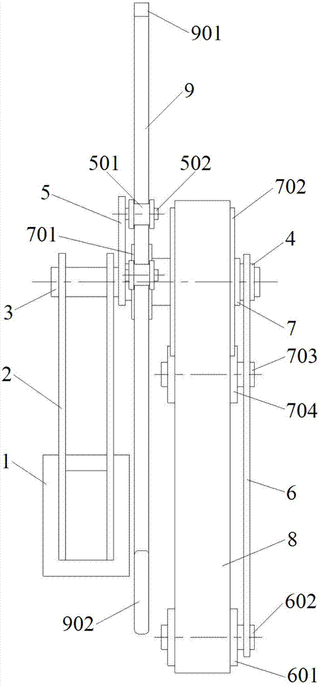
Figure 1 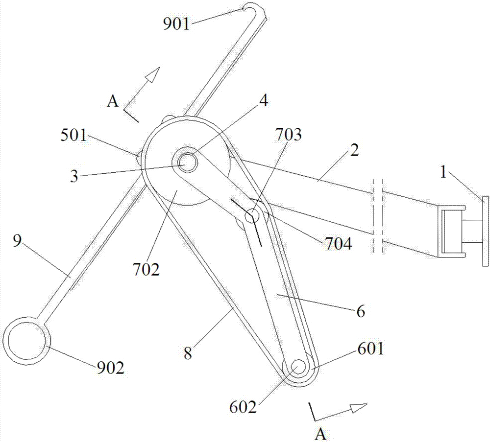
Figure 2 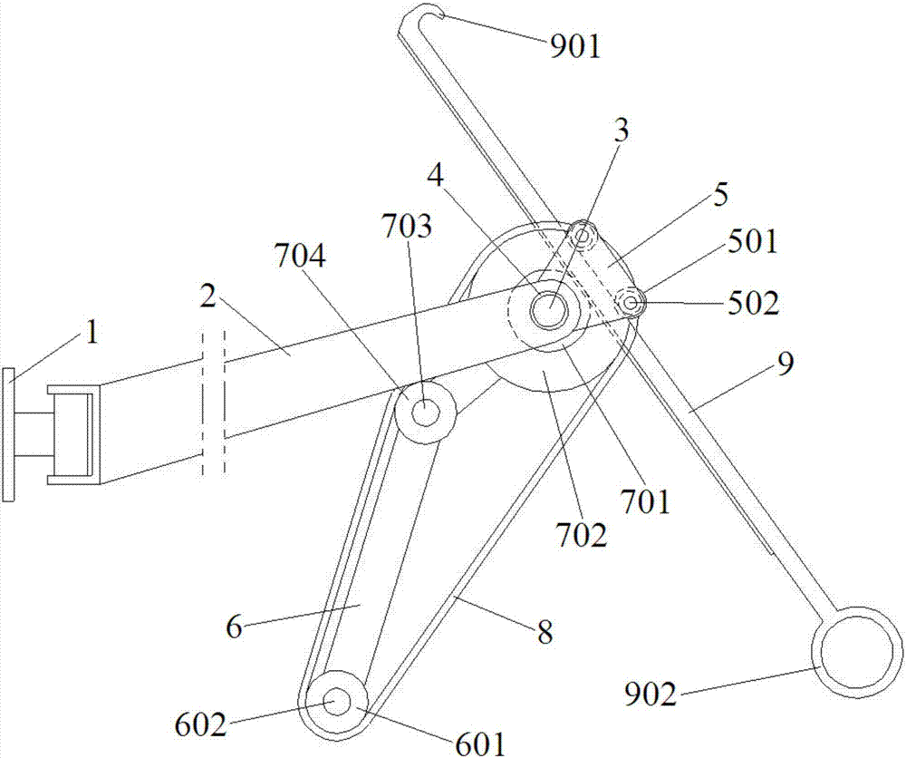
Figure 3
Abstract
Description
technical field
[0001] The invention belongs to the field of bathing equipment, and in particular relates to a manual bathing back rubbing device. Background technique
[0002] When users take a bath, they often cannot rub their backs by themselves. Some bath towels with both hands can make people bathe with both hands. Even with a two-hand scrub towel, it is difficult to scrub the sunken spine, resulting in incomplete back scrubbing. There are also some people who have difficulty exerting force when using both hands to rub the bath towel, especially the elderly, and it is even more difficult to rub their backs. Even for young people, if the soles of the feet slip when using both hands to rub their backs, they will cause serious accidents due to inability to use both hands for emergency grasping during the slipping process. Contents of the invention
[0003] In order to solve the above problems, the present invention proposes a manual bathing back rubbing device, which a...
Examples
Embodiment Construction
[0030] refer to Figure 1 to Figure 5 , the embodiment of the present invention proposes a kind of manual bath rubbing device, comprises: base 1, first sleeve 4, second sleeve 7, scrub belt 8 and rack 9, hinged on the base 1 There is a horizontal swing frame 2, the end of the horizontal swing frame 2 is horizontally fixed with a first horizontal shaft 3; the first sleeve 4 is rotatably fitted on the first horizontal shaft 3, and the first sleeve 4 One end of one end is fixedly connected with a swing control frame 5, and the other end is fixedly connected with a back rubbing frame 6. Two pressure rollers 501 are arranged to rotate side by side on the swing control frame 5, and a driven roller 501 is arranged to rotate side by side on the back rubbing frame 6. Pulley 601; the second sleeve 7 is rotatably set on the first sleeve 4, one end of the second sleeve 7 is fixedly connected with a driving gear 701, and the other end is fixedly connected with a driving pulley 702; The ba...