
Communication pipeline anticorrosion device based on multiple anticorrosion device
A multi-layer anti-corrosion and pipeline technology, which is applied in cable installation and cable installation in underground pipelines, can solve the problems of being easily affected by humid air, poor protection effect, and easy damage to pipeline connections, and achieves increased moisture-proof effect , the effect of increasing work efficiency
Patent Information
- Authority / Receiving Office
- CN · China
- Patent Type
- Applications(China)
- Current Assignee / Owner
- Publication Date
- 2018-01-19
Smart Images
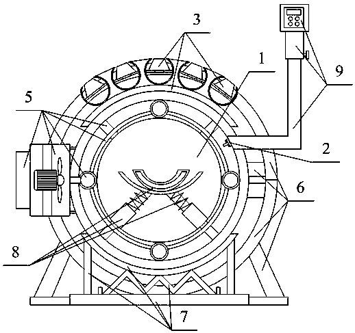
Figure 1 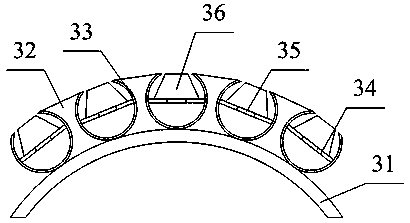
Figure 2 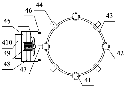
Figure 3
Abstract
Description
technical field
[0001] The invention belongs to the technical field of communication pipeline protection equipment, and in particular relates to communication pipeline anticorrosion equipment based on multiple anticorrosion devices. Background technique
[0002] With the rapid development of urban communication cable underground pipelines, the corrosion and protection problems of pipelines have become increasingly prominent. During the use of buried pipelines, due to long-term buried underground, they are prone to corrosion due to the underground environment. It will cause a great impact, and after the communication pipeline is corroded, the maintenance is troublesome and the maintenance cost is high. The existing technology is a technical solution adopted by a communication pipeline anticorrosion device with the Chinese Patent Publication No. 201520852904.7: including the communication pipeline. An anti-corrosion structure is set on the periphery of the communication pipeli...
Examples
Embodiment
[0042] as attached figure 1 to attach Figure 7 shown
[0043] The present invention provides a communication pipeline anticorrosion device based on multiple anticorrosion devices, including a pipeline main body 1, a humidity sensor 2, a waterproof drainage pipe structure 3, an air suction pipe structure 4, a controller structure 5, a protective plate structure 6, and a protective base structure 7 , a decompression seat structure 8 and a protective pipe 9, the humidity sensor 2 is installed on the upper right part of the inner wall of the protective pipe 9; the waterproof drain pipe structure 3 is placed on the top of the outer wall of the protective pipe 9; the suction pipe The structure 4 is installed between the pipeline main body 1 and the protective pipeline 9; the controller structure 5 is welded on the upper right part of the protective pipeline 9; the protective plate structure 6 is sleeved on the outer wall of the protective pipeline 9; the described The protective ...