
Method for manufacturing solid component and solid component
A technology of solid components and components, applied in the direction of tools, manufacturing tools, bearing components, etc. for lathes, and can solve problems such as high manufacturing costs
Patent Information
- Authority / Receiving Office
- CN · China
- Patent Type
- Patents(China)
- Current Assignee / Owner
- Publication Date
- 2020-08-21
Smart Images
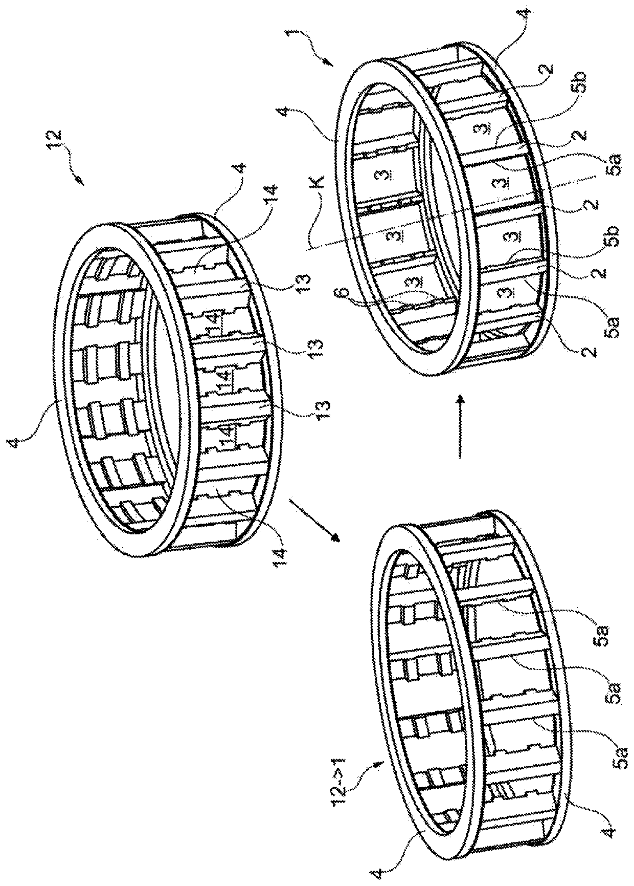
Figure 1 
Figure 2 
Figure 3
Abstract
Description
technical field
[0001] The invention relates to a method for producing a solid component and to a solid component produced by means of the method. Background technique
[0002] Cages in rolling bearings serve the purpose of: guiding the rolling elements and spacing them apart from one another. The cage is generally designed to be annular and has windows in which the rolling bodies are arranged. In addition to plastic cages and sheet metal cages, so-called solid cages are known which are produced from a solid semi-finished product by means of a separation method. In addition to the high material requirements for the solid cage, the separate machining in particular entails high manufacturing costs, since the windows are usually milled out one after the other.
[0003] Another solution for producing a solid cage is proposed in reference DE 40 34 516 C2, which perhaps forms the closest prior art. In this reference, a method is described in which the workpiece and the cutting ...
Examples
Embodiment Construction
[0044] figure 1 shown for manufacture as in the figure 1 A schematic overview of the method of a solid cage 1 as a solid component is shown at the bottom right. The solid cage 1 is designed for insertion into a rolling bearing and has a plurality of webs 2 as intermediate regions, which are arranged regularly distributed in the circumferential direction about the axis of rotation K of the cage. Between the webs 2 there are respectively pockets 3 for accommodating rolling bodies, which are rollers in this example. Side rings 4 are arranged on the axial end side, wherein the webs 2 and / or the pockets 3 extend between the side rings 4 . The solid cage 1 is formed in one piece.
[0045] Each web 2 has a first web side 5a as the first pocket side and a second web side 5b as the second pocket side. exist figure 1 In the embodiment shown in , the first tab side is oriented clockwise and the second tab side is oriented counterclockwise. For reasons of clarity, only two webs 2 ar...