
A Generalized Droop Control Method
A control method, a generalized technology, applied in the direction of reducing/preventing power oscillations, etc., can solve problems such as increased construction costs, main power overload, system voltage, frequency fluctuations, etc., to achieve reduced construction costs, lower requirements, and large adjustment margins Effect
Patent Information
- Authority / Receiving Office
- CN · China
- Patent Type
- Patents(China)
- Current Assignee / Owner
- Publication Date
- 2022-03-29
Smart Images
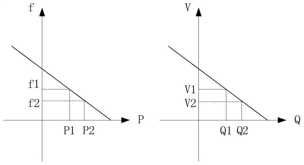
Figure 1 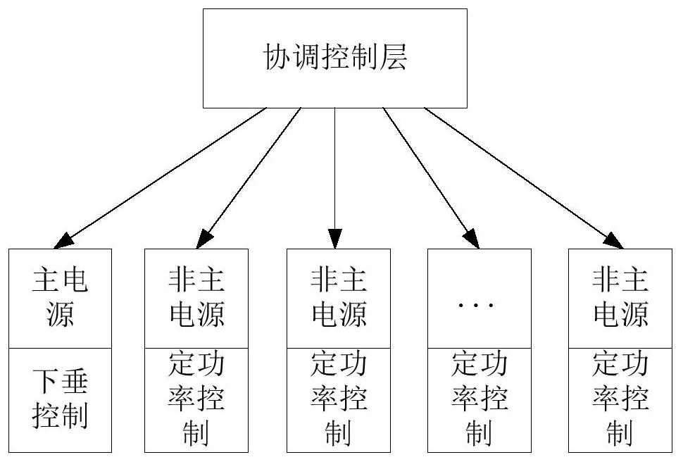
Figure 2 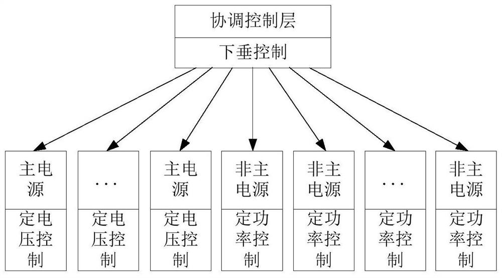
Figure 3
Abstract
Description
technical field
[0001] The invention relates to a power control method for a power source, which is suitable for a micro grid or an isolated grid. Background technique
[0002] A microgrid or isolated grid consists of power sources, transmission lines, transformers and loads. In order to keep the voltage and frequency of the power grid stable, in the traditional control method, it is necessary to designate a power supply as the main power supply, and implement a droop control strategy in the main power supply, that is, a control strategy in which the active power is inversely proportional to the frequency, and the reactive power is inversely proportional to the voltage. principle such as figure 1 As shown; other power sources in the grid adopt a constant power control strategy. Traditional control schemes such as figure 2 shown.
[0003] When the grid has disturbances such as load fluctuations, power trips, etc., the main power supply in the grid absorbs this part of th...
Examples
Embodiment 1
[0022] Example 1: In a microgrid, including power source A, power source B, power source C, power source D and coordination control layer device X, according to image 3 According to the scheme, power supply A and power supply B are set as the main power supply, and the constant voltage control strategy is implemented; power supply C and power supply D are set as non-main power supplies, and the constant power control strategy is implemented; the droop control strategy is implemented in the coordination control layer device X; the total load for P LD and Q LD , where P LD Include the network power loss, Q LD Include the charging power of the network; the total load at the next moment becomes P LD1 and Q LD1 , then the total power output is P LD1 and Q LD1 .
[0023] In the method of the present invention, according to Figure 4 The control flow diagram, the control steps are as follows:
[0024] (1) Detect all power output and system voltage, coordinate the control la...