
Special wire rope winding bracket
A steel wire rope and special technology, applied in the field of steel wire rope, can solve the problems of affecting the appearance, affecting the handling and use, etc., to achieve the effect of easy movement and easy winding
Patent Information
- Authority / Receiving Office
- CN · China
- Patent Type
- Applications(China)
- Current Assignee / Owner
- Publication Date
- 2019-01-15
Smart Images
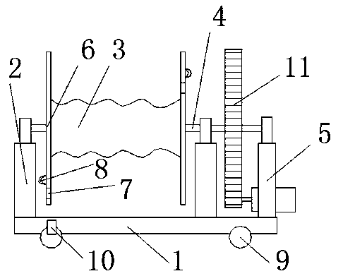
Figure 1
Abstract
Description
technical field
[0001] The invention relates to the technical field of steel wire ropes, in particular to a special winding support for steel wire ropes. Background technique
[0002] The winch is a device used for traction. The wire rope of the winch is wound on the reel, and the reel is driven by the driving device to realize the rapid soft winding or release of the wire rope. In the existing wire rope winding device, the winding of the wire rope will leave the head of the wire rope idle there, which affects the appearance, and also affects the handling and use.
[0003] Therefore, a new technical solution needs to be sought to solve the above problems. Contents of the invention
[0004] The object of the present invention is to provide a special wire rope winding support.
[0005] In order to achieve the above object, the technical scheme adopted in the present invention is:
[0006] A special steel wire rope winding support, including a support base, a fixing frame ...
Examples
Embodiment 1
[0013] Such as figure 1 As mentioned above, a special wire rope winding support of the present invention includes a support base 1, a fixing frame 2 is arranged on the support base 1, a winding support body 3 is arranged between the fixing frames 2, and the winding support body 3 is arranged between the fixing frames 2. The winding support body 3 is connected to the fixed frame 2 through the rotating shaft 4, one side of the winding support body 3 is connected to the turntable 11, and one side of the turntable 11 is connected to the rotating shaft 5, and the side disks 6 on both sides of the winding support body 3 A perforation 7 is provided on the top, and a ring hole 8 matching the perforation 7 is provided on the outside of the side plate 6 .
[0014] A sliding wheel 9 is arranged under the support base 1 , and a brake pad 10 is arranged on the sliding wheel 9 .
[0015] The winding support body 3 is a wave-shaped reel.
[0016] In the above technical solution, compared w...