
An Adaptive Blade Angle Measuring Instrument
An angle measurement and self-adaptive technology, applied in the direction of angle/taper measurement, etc., can solve problems such as the complex structure of the detection method and the impact on the processing efficiency of the enterprise, and achieve the effect of reducing manual labor and improving detection efficiency
Patent Information
- Authority / Receiving Office
- CN · China
- Patent Type
- Patents(China)
- Current Assignee / Owner
- Publication Date
- 2021-03-26
Smart Images
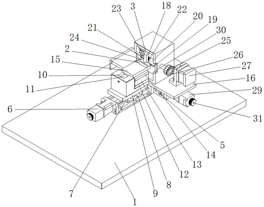
Figure 1 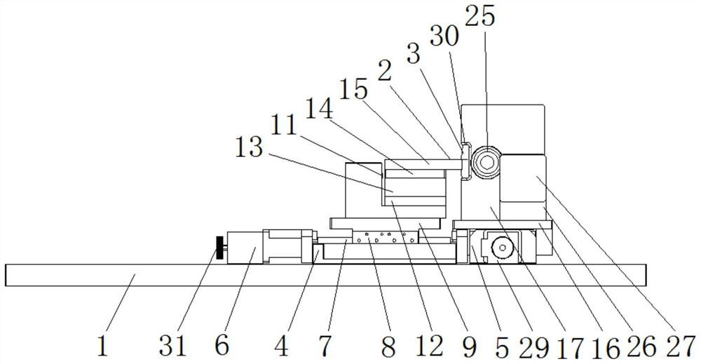
Figure 2 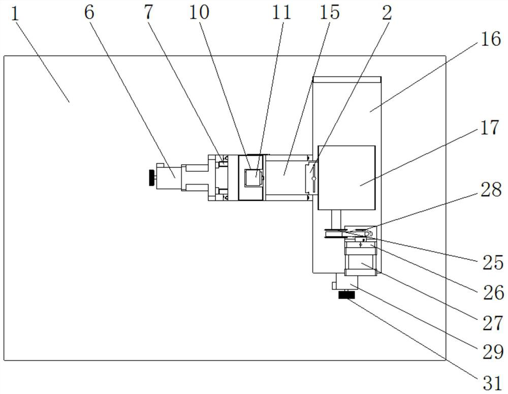
Figure 3
Abstract
Description
technical field
[0001] The invention relates to the technical field of blade testing equipment, in particular to an adaptive blade angle measuring instrument. Background technique
[0002] There are many types of blades, which can generally be divided into standard parts and non-standard parts. Usually, non-standard blades are called special-shaped blades, such as Feihong special-shaped blades. If they are divided according to their shape, they can be divided into straight-edged blades and special-shaped , pointed blades, arc blades, toothed blades, corrugated blades and inscribed circular blades), etc., if classified according to the purpose, they can be divided into medical equipment blades, industrial blades, food blades, etc. There are many factors that affect the quality of blades, including Knife body material, processing technology and blade angle, etc.
[0003] Wherein the angle of the blade is large and the blade will not be sharp, and the blade angle will seriousl...
Examples
Embodiment Construction
[0024] The following will clearly and completely describe the technical solutions in the embodiments of the present invention with reference to the accompanying drawings in the embodiments of the present invention. Obviously, the described embodiments are only some, not all, embodiments of the present invention. Based on the embodiments of the present invention, all other embodiments obtained by persons of ordinary skill in the art without making creative efforts belong to the protection scope of the present invention.
[0025] see Figure 1-3, the embodiment of the present invention provides a technical solution: an adaptive blade angle measuring instrument, including a fixed base plate 1, a blade 2 and a soft rubber belt 3, and the top of the fixed base plate 1 is fixedly connected with an X-axis through bolts from left to right in sequence The connecting plate 4 and the Y-axis connecting plate 5, the left side of the X-axis connecting plate 4 is fixedly connected with the X...