
Zero oil swap energy conversion valve with double hydraulic systems
A technology of energy conversion and zero leakage of oil, which is applied in the direction of fluid pressure actuators, servo motor components, mechanical equipment, etc., can solve the problems of danger, difficulty in inspection, etc., and achieve reliable oil supply, solve leakage, and flexible conversion Effect
Patent Information
- Authority / Receiving Office
- CN · China
- Current Assignee / Owner
- Publication Date
- 2020-02-28
Smart Images
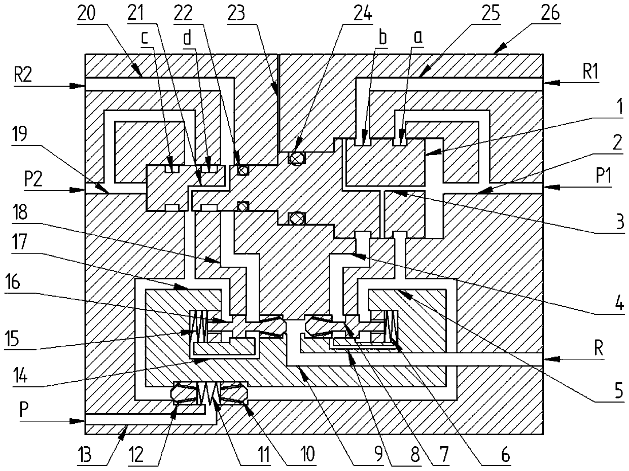
Figure 1 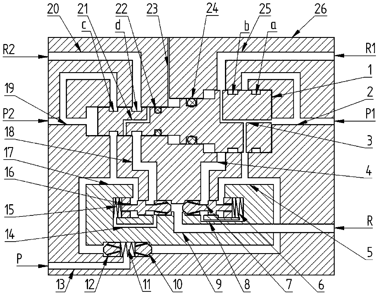
Figure 2
Abstract
Description
technical field
[0001] The invention relates to a double-hydraulic system zero-splash oil energy conversion valve, in particular to switch between a normal pressure supply oil circuit and an emergency pressure supply oil circuit connected to an aircraft, and ensure zero-spray oil between the two oil circuits during switching. Background technique
[0002] There are usually more than three sets of hydraulic systems on an aircraft, and it is generally impossible for three sets to be damaged at the same time. In the event of total damage, the aircraft immediately seeks the nearest location for landing repairs. If "all the hydraulic systems fail", then the aircraft's mechanisms that could have been able to move will not be able to move, and the flight status cannot be changed. The function of the hydraulic system is to increase the force by changing the pressure. A complete hydraulic system consists of five parts, namely power components, actuators, control components, auxilia...
Examples
Embodiment Construction
[0014] refer to Figure 1 ~ Figure 2. In the preferred embodiment described below, a dual-hydraulic system zero-sequence oil energy conversion valve includes: a valve body 26 of a dual-hydraulic system that communicates with the normal pressure oil circuit and the emergency pressure oil circuit, assembled on the valve body 26 The shaft shoulders with different heights are restricted in the cavity, and the step slide valve 1 moves along the axis direction or the movement trend, and each section of the step slide valve 1 is respectively formed with annular grooves a, b, c, d and sealing ring groove, it is characterized in that: the unloading hole 23 connected to the stepped hole of the valve cavity is formed on the valve body 26, and the upper body of the valve cavity of the head and tail stepped holes is symmetrical to each other, and the radial direction corresponds to the annular groove a, b, c , d are bent upwards in parallel, respectively connected to the second oil inlet ...