
Self-cleaning glue spraying machine
A glue spraying machine and self-cleaning technology, which is applied in the field of glue spraying machines, can solve the problems of low cleaning efficiency, increase labor intensity of workers, and affect the working efficiency of glue spraying machines, so as to improve glue spraying efficiency, clean up conveniently and quickly, and lower The effect of cleaning time
Patent Information
- Authority / Receiving Office
- CN · China
- Patent Type
- Applications(China)
- Current Assignee / Owner
- Publication Date
- 2020-04-24
Smart Images
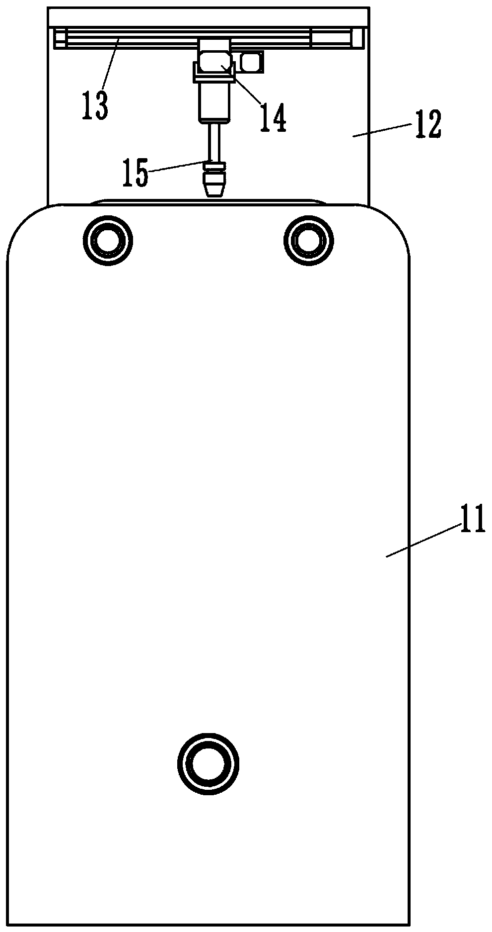
Figure 1 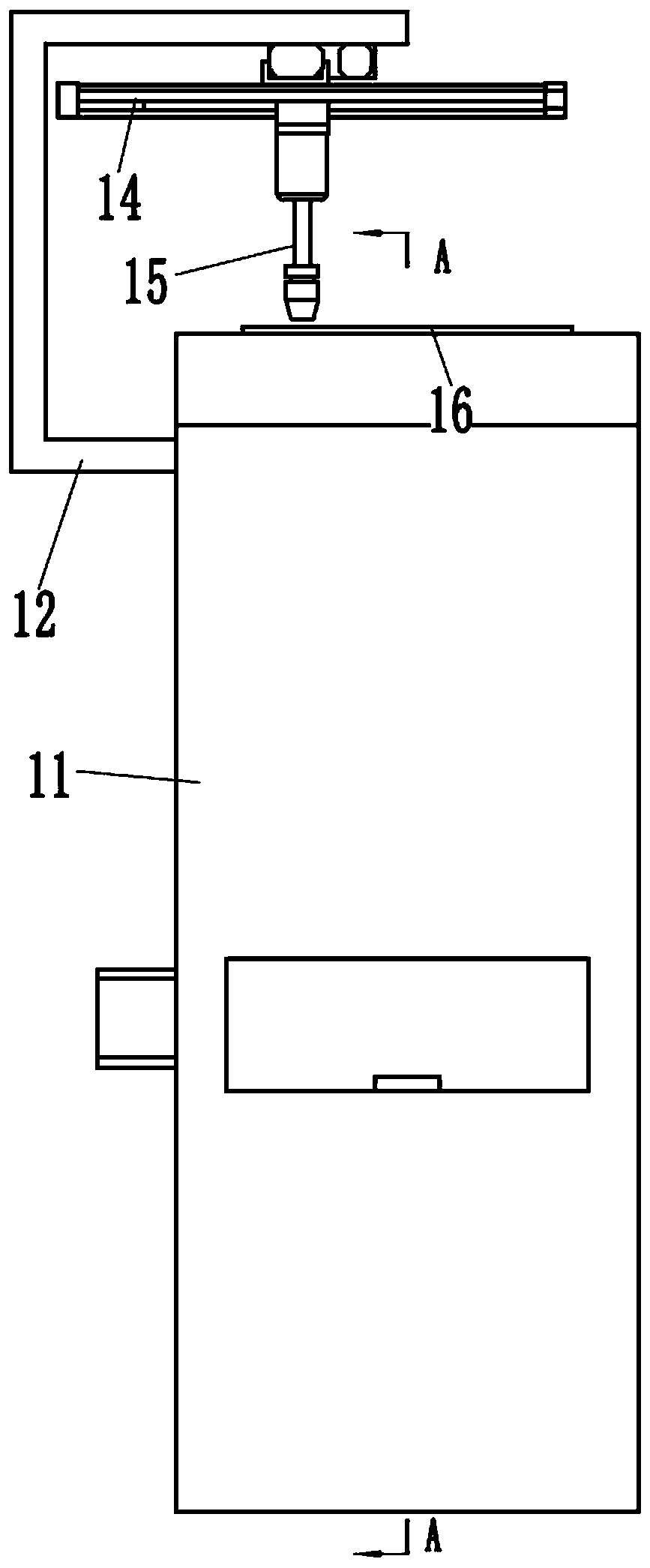
Figure 2 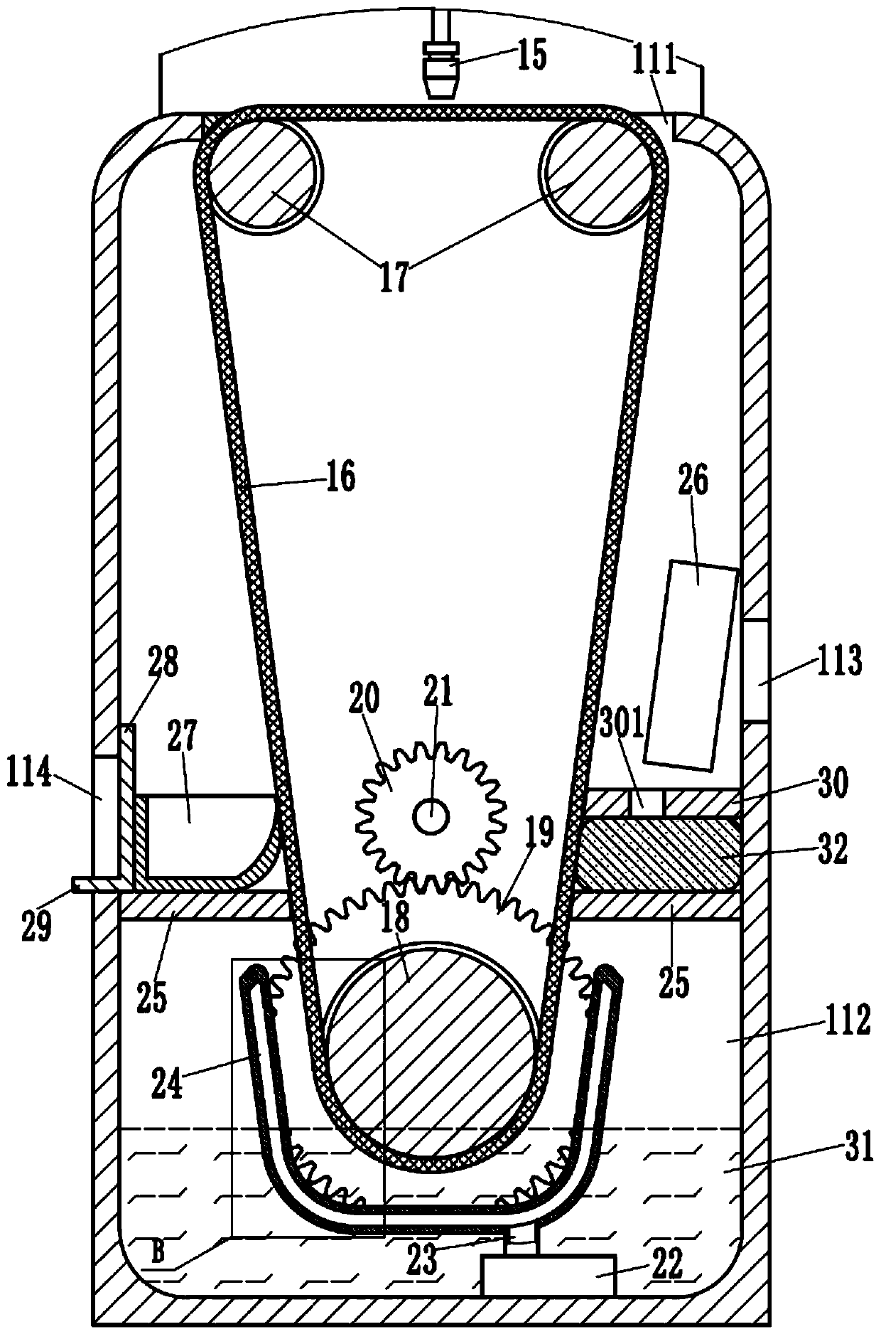
Figure 3
Abstract
Description
Technical field:
[0001] The invention relates to the technical field of glue spraying machines, in particular to a self-cleaning glue spraying machine. Background technique:
[0002] As a common equipment, the glue spraying machine is used to heat the solid glue into glue and then spray it on the surface of the object, so as to form a glue layer on the surface of the object to realize the protection of the object. However, during the process of spraying the surface of the object by the glue spraying machine, the glue will leak sideways onto the glue spraying panel containing the object, requiring workers to clean it manually. The cleaning efficiency is low and the labor intensity of the workers is also increased, which affects the glue spraying. machine efficiency. Invention content:
[0003] The purpose of the present invention is to overcome the deficiencies of the prior art, and provide a self-cleaning glue spraying machine, which uses a support belt to replace the glu...
Examples
Embodiment Construction
[0015] Examples, see e.g. Figure 1 to Figure 4 As shown, a self-cleaning glue spraying machine includes a chassis 11, a frame 12 is fixed on the rear side wall of the chassis 11, an X-axis linear module 13 is fixed on the frame 12, and the first X-axis linear module 13 A Y-axis linear module 14 is fixed on the slider, and a glue spray head 15 is fixed on the second slider of the Y-axis linear module 14. A gap 111 is formed on the upper side wall of the chassis 11. The glue spray head 15 The bottom of the belt is provided with a support belt 16, and the support belt 16 is tensioned on two driven pulleys 17 and a driving pulley 18 arranged at the same height, and the driving pulley 18 is located below the middle of the two driven pulleys 17, The two ends of driving pulley 18 and two driven pulleys 17 are respectively hinged on the front side wall and the rear side wall of cabinet 11; On the upper end surface of the gap 111, the rear end of the driving pulley 18 is fixed with a...