
Injection mold for automobile air guide plate
A technology of injection mold and air deflector, which is applied to household appliances, other household appliances, household components, etc., to achieve the effect of improving work efficiency
Patent Information
- Authority / Receiving Office
- CN · China
- Patent Type
- Applications(China)
- Current Assignee / Owner
- Publication Date
- 2020-05-19
Smart Images
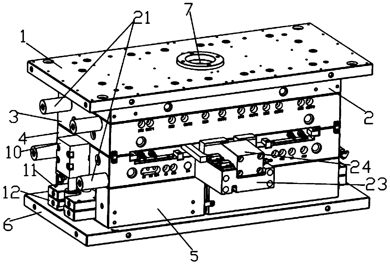
Figure 1 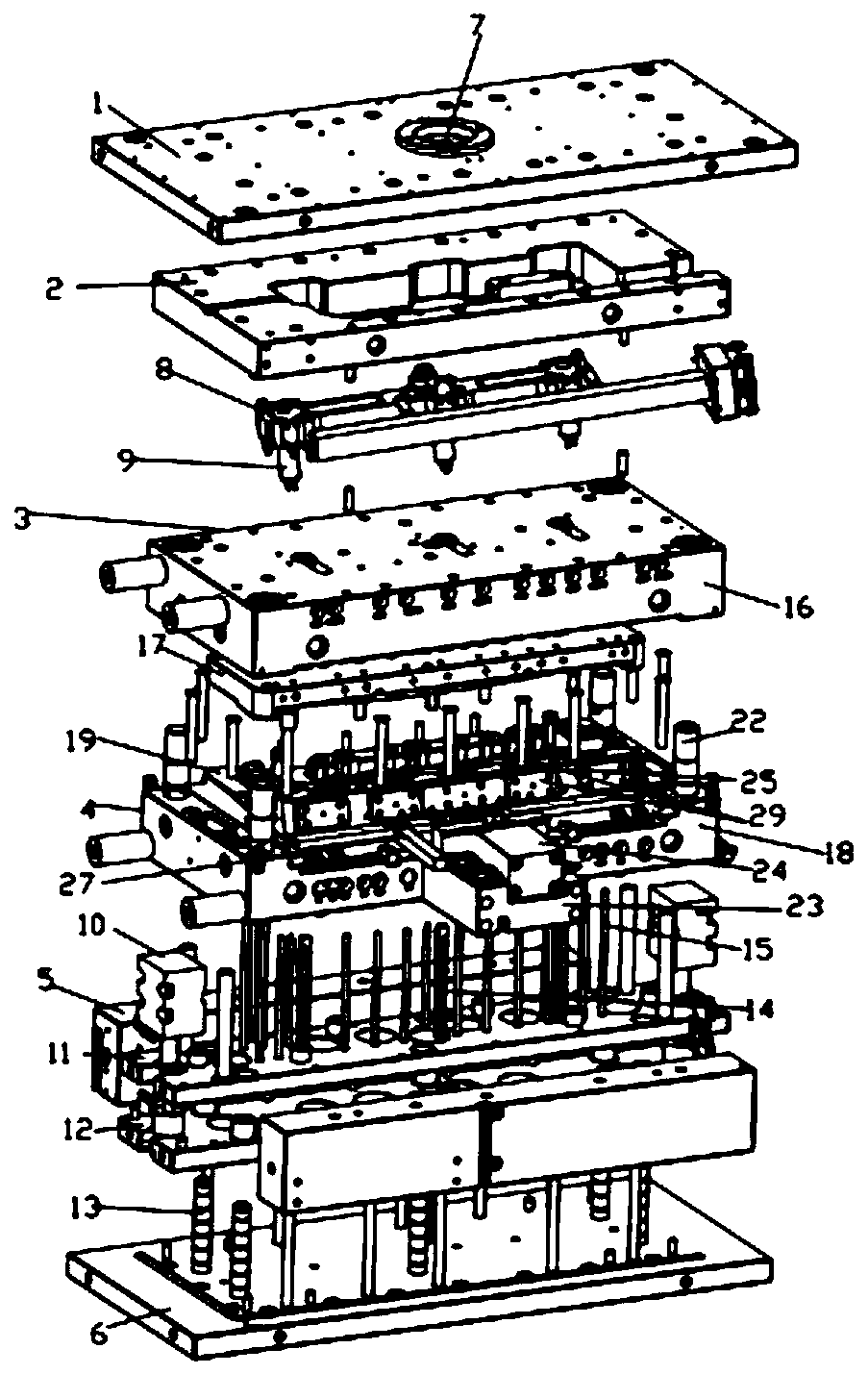
Figure 2 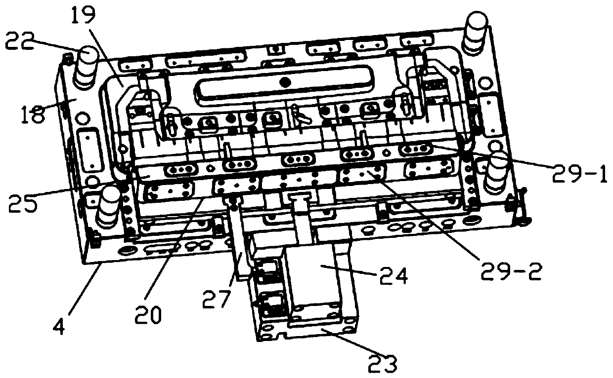
Figure 3
Abstract
Description
technical field
[0001] The invention discloses the technical field of injection molds, and more specifically discloses an injection mold for an automobile wind deflector. Background technique
[0002] At present, with the development of the automobile industry, during the driving process of the vehicle, the automobile air deflector can gather the air to the maximum extent, so that the air can quickly take away the heat through the condensing device to reduce the temperature of the working parts of the vehicle, and at the same time avoid the airflow disorder inside the cabin With the diversification of automobiles, the driving conditions of automobiles are becoming more and more complicated. What's more, some off-road models may often drive in harsh working conditions such as mud, gravel, and high slopes. Therefore, the wind deflectors of automobiles will There are reinforcing ribs, the purpose of which is to increase the hardness of the automobile wind deflector. However, du...
Examples
Embodiment Construction
[0022] The specific implementation manners of the present invention will be further described below in conjunction with the accompanying drawings, so as to make the technical solution of the present invention easier to understand and grasp.
[0023] Such as Figure 1 to Figure 5 As shown, an injection mold for an automobile wind deflector includes a top plate 1, a hot runner plate 2, a fixed mold mechanism 3, a movable mold mechanism 4, a mold foot 5 and a bottom plate 6, and the bottom plate 6 is connected to the movable mold mechanism through the mold foot 5. 4, the movable mold mechanism 4 is located below the fixed mold mechanism 3, the fixed mold mechanism 3 is connected with the top plate 1 through the hot runner plate 2, the top plate 1 is provided with a gate 7, and the gate 7 A diverter plate 8 is connected, and the diverter plate 8 is fixed in the hot runner plate 2, and two or more hot nozzles 9 are arranged on the diverter plate 8, and one end of the nozzle 9 is co...