
Safety guardrail with adjustable protection height
A safety guardrail and height technology, applied in road safety devices, roads, roads, etc., can solve the problems of guardrail knocked down, height can not be adjusted, weak anti-collision ability, etc., achieve adjustable angle, simple and convenient operation, and reduce operation effect of difficulty
Patent Information
- Authority / Receiving Office
- CN · China
- Patent Type
- Applications(China)
- Current Assignee / Owner
- Publication Date
- 2021-01-01
- Estimated Expiration
- Not applicable · inactive patent
Smart Images
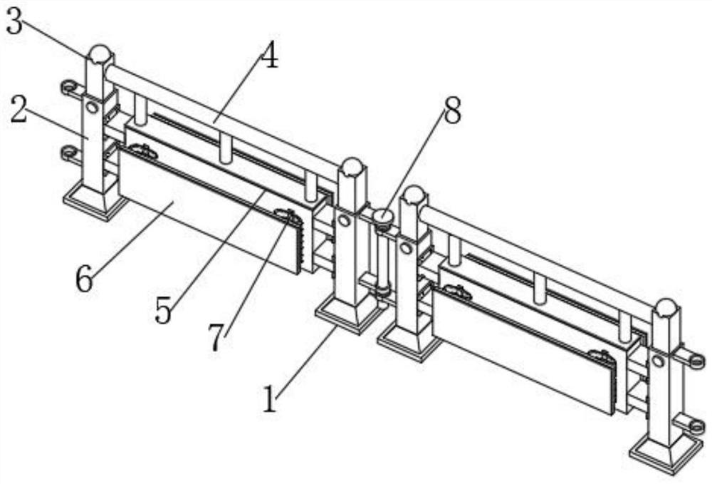
Figure 1 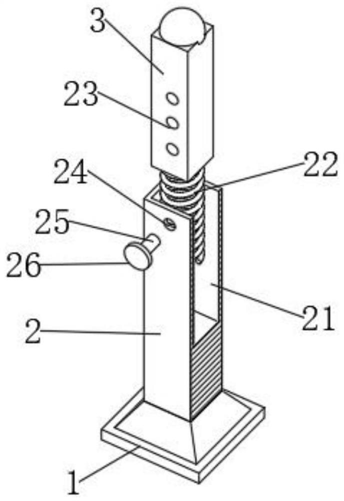
Figure 2 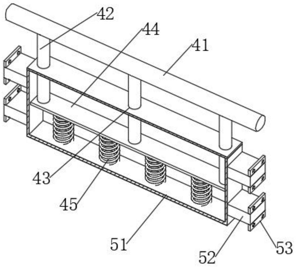
Figure 3
Abstract
Description
technical field
[0001] The invention relates to the field of protection facilities, in particular to a safety guardrail capable of adjusting the protection height. Background technique
[0002] With the continuous development of the economy and society, the continuous improvement of people's living standards, and the continuous increase in the number of motor vehicles, protective fences are often used to divide the roads in urban roads to ensure safety and smooth traffic.
[0003] The road guardrail belongs to the public transportation infrastructure, and it is an important guarantee facility for maintaining and protecting road safety. The function of the road guardrail on the road is to distinguish lanes, ensure that vehicles drive according to the lane, and ensure traffic safety. At the same time, it can also block the headlights of the opposite lane at night, further ensuring the safety of driving. Most of the current guardrails are made up of many cut small guardrails p...
Examples
Embodiment Construction
[0024] In order to make the technical means, creative features, goals and effects achieved by the present invention easy to understand, the present invention will be further described below in conjunction with specific embodiments.
[0025] In the description of the present invention, it should be noted that the terms "upper", "lower", "inner", "outer", "front end", "rear end", "both ends", "one end", "another end" The orientation or positional relationship indicated by etc. is based on the orientation or positional relationship shown in the drawings, and is only for the convenience of describing the present invention and simplifying the description, rather than indicating or implying that the referred device or element must have a specific orientation, use a specific Azimuth configuration and operation, therefore, should not be construed as limiting the invention. In addition, the terms "first" and "second" are used for descriptive purposes only, and should not be understood ...