
Self-rotation type aircraft and interaction method based on self-rotation type aircraft
A technology for an aircraft and a flying device, applied in the field of flying toys, can solve the problem of not meeting the needs of users, and achieve the effect of enhancing the fun of interaction and meeting the needs of use.
Patent Information
- Authority / Receiving Office
- CN · China
- Current Assignee / Owner
- Publication Date
- 2022-01-11
Smart Images
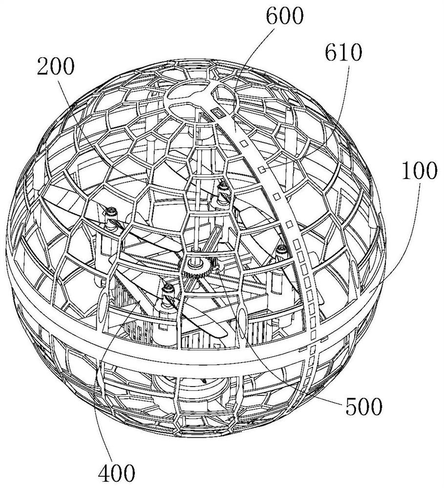
Figure 1 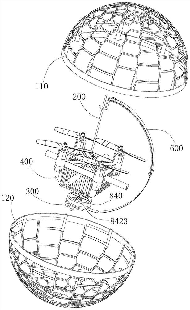
Figure 2 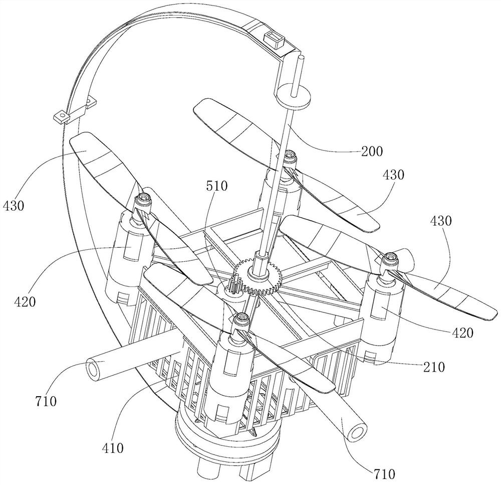
Figure 3
Abstract
Description
technical field
[0001] The invention belongs to the technical field of flying toys, and in particular relates to an autorotating aircraft and an interaction method based on the autorotating aircraft. Background technique
[0002] With the improvement of people's living standards, the functional requirements of toys are getting higher and higher, and flying toys have emerged as the times require. For example, the utility model patent with the application number CN201721262985.0 discloses a LED spherical display with a drone, including: an outer frame, a display module, a drone and a power unit; the display module is fixed in rotation In the frame, the drone and the power unit are arranged in the display module; the drone drives the outer frame and the display module and the power unit in the outer frame to fly; the power unit drives the display module around its own axis Heart turns.
[0003] Although the LED spherical display screen with drone disclosed in the above-mentio...
Examples
Embodiment Construction
[0039] Embodiments of the present invention are described in detail below, examples of which are shown in the drawings, wherein the same or similar reference numerals designate the same or similar elements or elements having the same or similar functions throughout. The embodiments described below by referring to the figures are exemplary and are intended to explain the embodiments of the present invention and should not be construed as limitations of the present invention.
[0040]In the description of the embodiments of the present invention, it should be understood that the terms "length", "width", "upper", "lower", "front", "rear", "left", "right", "vertical ", "horizontal", "top", "bottom", "inner", "outer" and other indicated orientations or positional relationships are based on the orientations or positional relationships shown in the drawings, and are only for the convenience of describing the embodiments of the present invention and simplifying Describes, but does not...