
Optical disk device
An optical disc device and optical technology, which is applied to the configuration/installation of heads, recording/reproducing by optical methods, instruments, etc., can solve the problems of increasing operating hours, affecting the simplification of assembly, etc., so as to reduce operating hours and prevent falling off. Effect
Patent Information
- Authority / Receiving Office
- CN · China
- Patent Type
- Applications(China)
- Current Assignee / Owner
- Publication Date
- 2006-05-03
- Estimated Expiration
- Not applicable · inactive patent
Smart Images
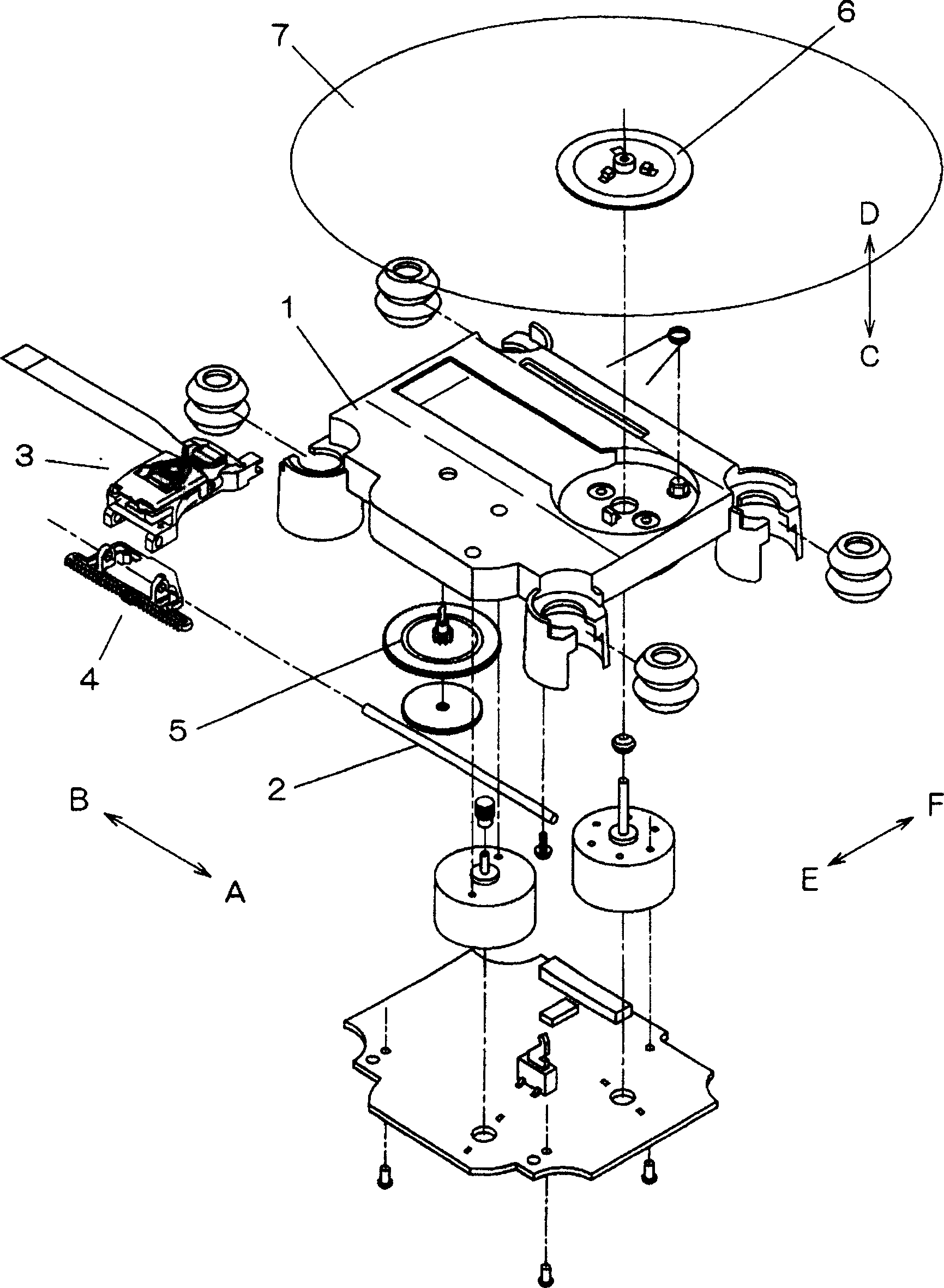
Figure 1 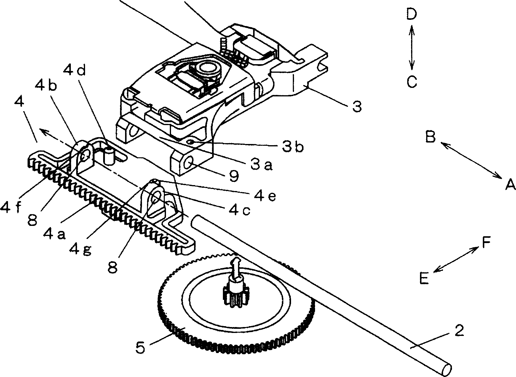
Figure 2 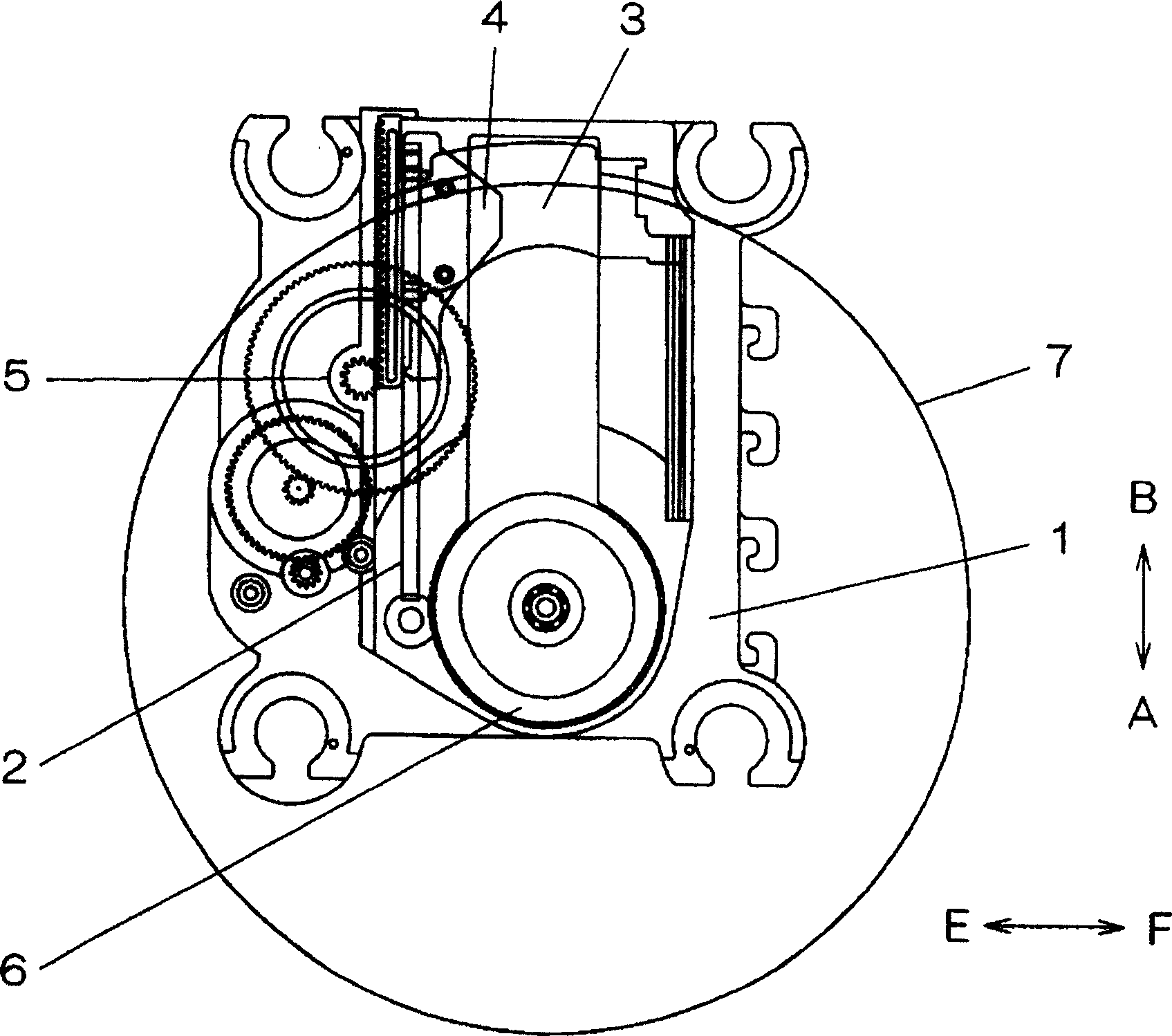
Figure 3
Abstract
Description
technical field
[0001] The present invention relates to an optical disc device which has a simple structure by reducing the number of parts. Background technique
[0002] The pickup driving mechanism for recording and reproducing on the optical disc is composed of a guide part, an optical pickup, a feed rack and a feed gear. The rack is firmly connected to the optical pickup and driven by the feed gear. For recording and reproduction of an optical disc, it is necessary to precisely control the feed amount of the optical pickup, and a structure to absorb the meshing gap between the feed gear and the feed rack is required. Usually, the rack portion of the feed rack is formed of resin, and the bending of the rack portion increases the meshing amount on the pitch line by virtue of the elasticity of the resin, thereby absorbing the meshing gap. And, in order to precisely control the feeding amount of the optical pickup, it is necessary to use a connecting member to fix the opti...
Examples
Embodiment 1
[0022] Embodiments of the present invention will be described below with reference to the drawings. figure 1 It is an exploded perspective view of the part structure in the device embodiment of the present invention, figure 2 yes figure 1 A zoomed-in perspective view of the vicinity of the optical pickup in the middle, image 3 is a plan view after the device is assembled in the present invention, Figure 4 is a plan view near the turntable in the above embodiment, Figure 5 From Figure 4 The side view indicated by the arrow Z direction in the middle, Figure 6 From Figure 4 The side view shown in the arrow Y direction in the middle, in order to better understand the above description, shows the section near the optical pickup 3 and the rack 4 ( Figure 4 X-X section).
[0023]In the figure, 7 is a recording medium for recording various signals, that is, a disk, 3 is an optical pickup for recording and reproducing signals on the disk 7, and is composed of a lens and ...