
Self-supporting railway digital signal cable
A digital signal cable, self-supporting technology, applied in the direction of communication cables, insulated cables, cables, etc., can solve the problems of cumbersome construction and installation process, inconvenient construction, and long time consumption, so as to shorten the construction time, avoid trouble, and install quickly and conveniently Effect
Patent Information
- Authority / Receiving Office
- CN · China
- Patent Type
- Applications(China)
- Current Assignee / Owner
- Publication Date
- 2006-09-27
- Estimated Expiration
- Not applicable · inactive patent
Smart Images
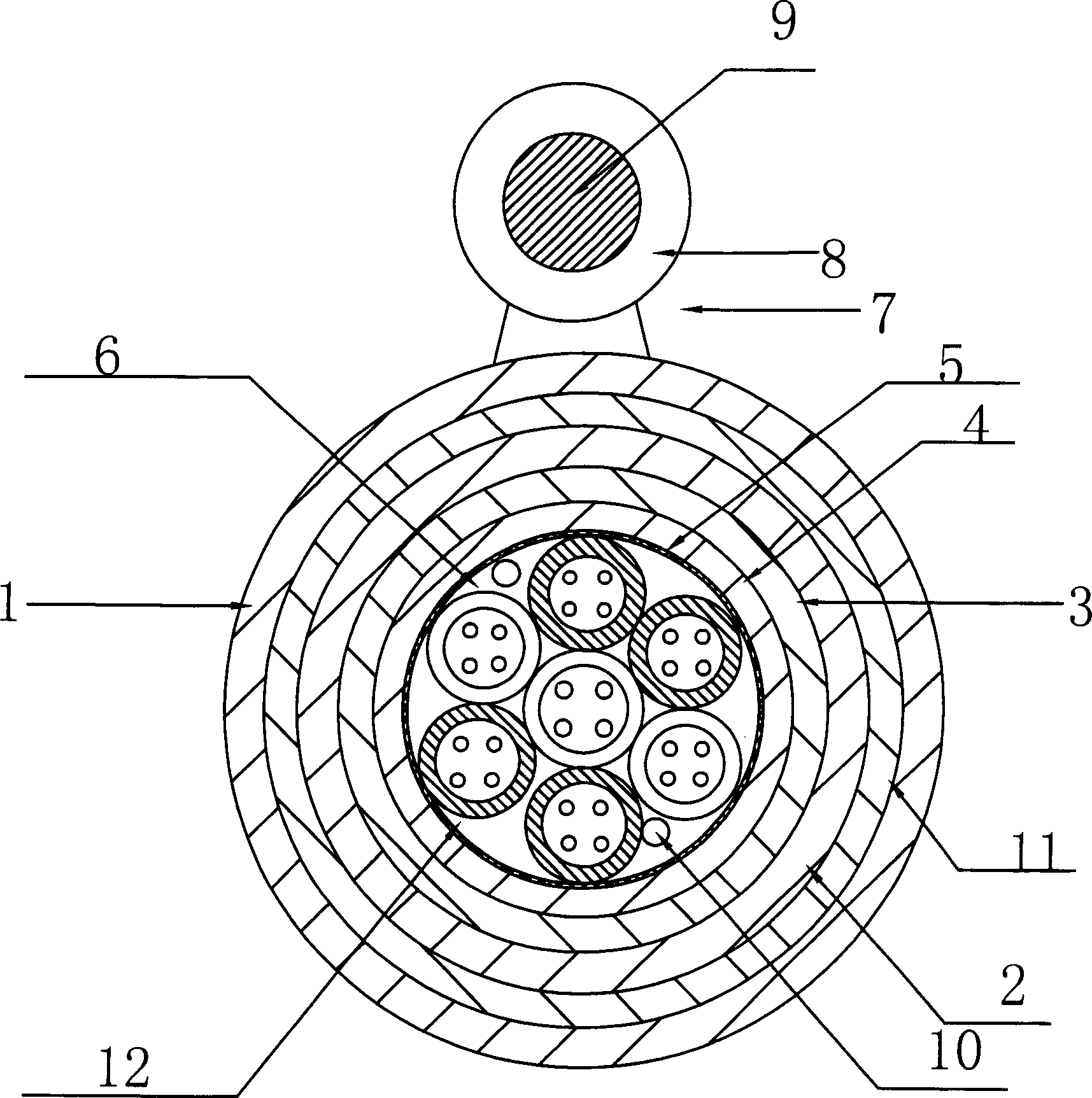
Figure 1 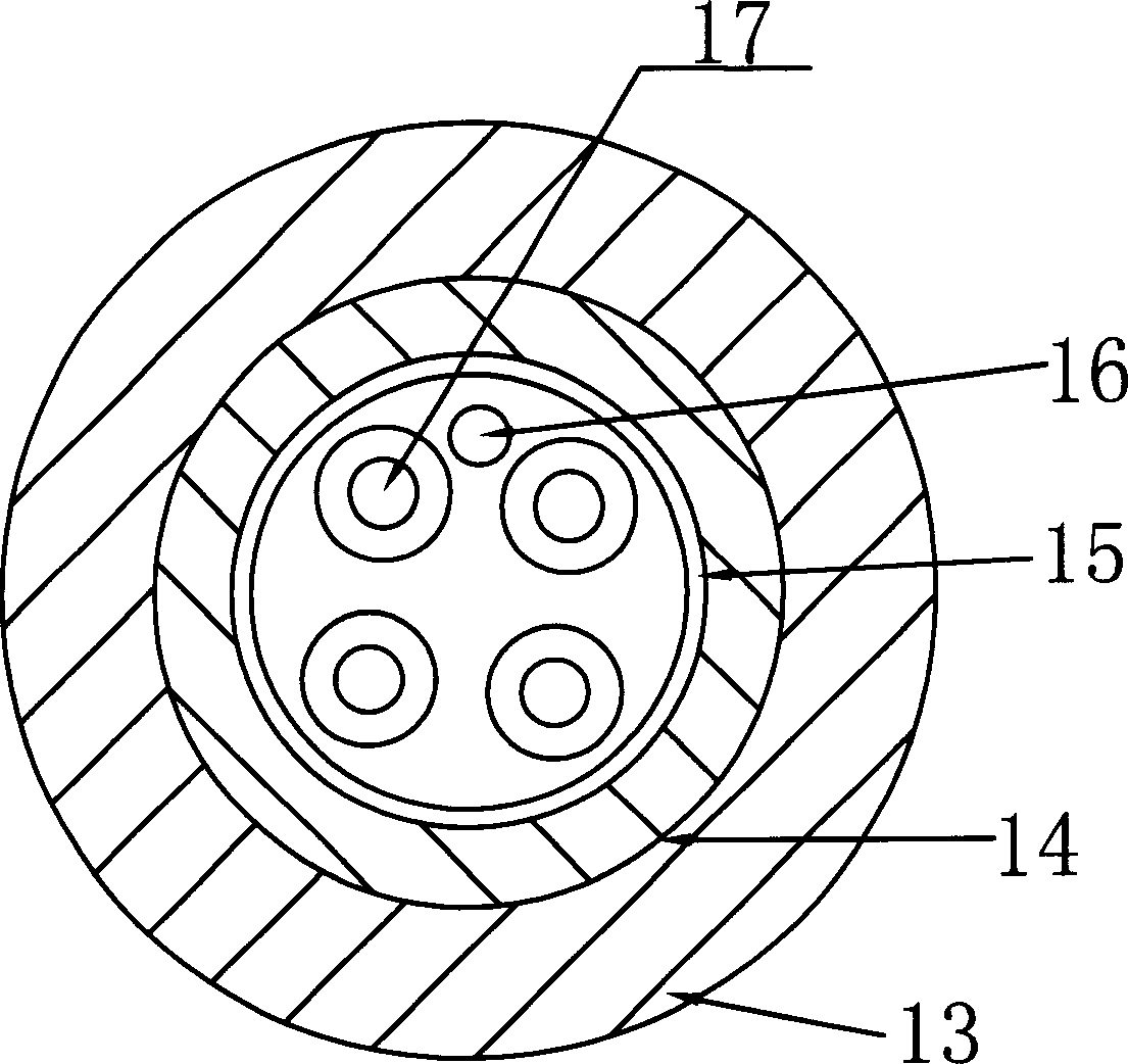
Figure 2 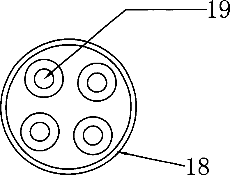
Figure 3
Abstract
Description
technical field
[0001] The invention relates to a railway digital signal cable. Background technique
[0002] Existing railway digital signal cables usually include a cable core, an insulating tape wrapped outside the cable core, and an outer sheath layer located outside the insulating tape. The cable core usually includes multiple sets of signal lines, and multiple sets of signal lines can be set as required It is an inner shielded four-wire group, an unshielded four-wire group or a combination of two signal lines. At present, the main installation methods of railway digital signal cables are direct burial, pipeline and suspension. Among them, the suspension method needs to first install a steel strand between two poles, and then place it at a certain distance on the steel strand. Several cable hooks are used to hang the installed railway digital signal cables, but in actual construction, special construction environments will be encountered, such...
Examples
Embodiment Construction
[0016] See attached figure 1 - attached Figure 7 As shown, a self-supporting railway digital signal cable includes a cable core, an insulating tape 4 wrapped outside the cable core, an outer sheath layer 1 positioned outside the insulating tape 4, and an attached figure 1 , attached Figure 5 In the shown embodiment, the outer side of the insulating tape 4 is wrapped with the aluminum-plastic composite tape 3 , and the outer sheath layer 1 is located on the outer side of the aluminum-plastic composite tape 3 . The cable core includes multiple sets of signal wires, and binding yarns 5 are wrapped on the outside of the multiple sets of signal wires. figure 1 , attached Figure 7 In the shown embodiment, part of the signal wires is an unshielded four-wire group 6, and part of the signal wires is an inner shielded four-wire group 12, and a pair of twisted wires 10 is also provided in the cable core. Figure 5 , attached Image 6 In the illustrated embodiment, there are unshi...