
Overload clutch
a technology of overloading and clutch, applied in the field of overloading clutch, can solve the problems of inadmissible stresses and overly intense shrinkage behavior of the encompassing ring, and achieve the effects of increasing the mechanical characteristics of injection-moulded parts, reducing shrinkage, and increasing the peripheral accommodation of load
Patent Information
- Authority / Receiving Office
- US · United States
- Patent Type
- Patents(United States)
- Current Assignee / Owner
- Publication Date
- 2020-06-16
Smart Images
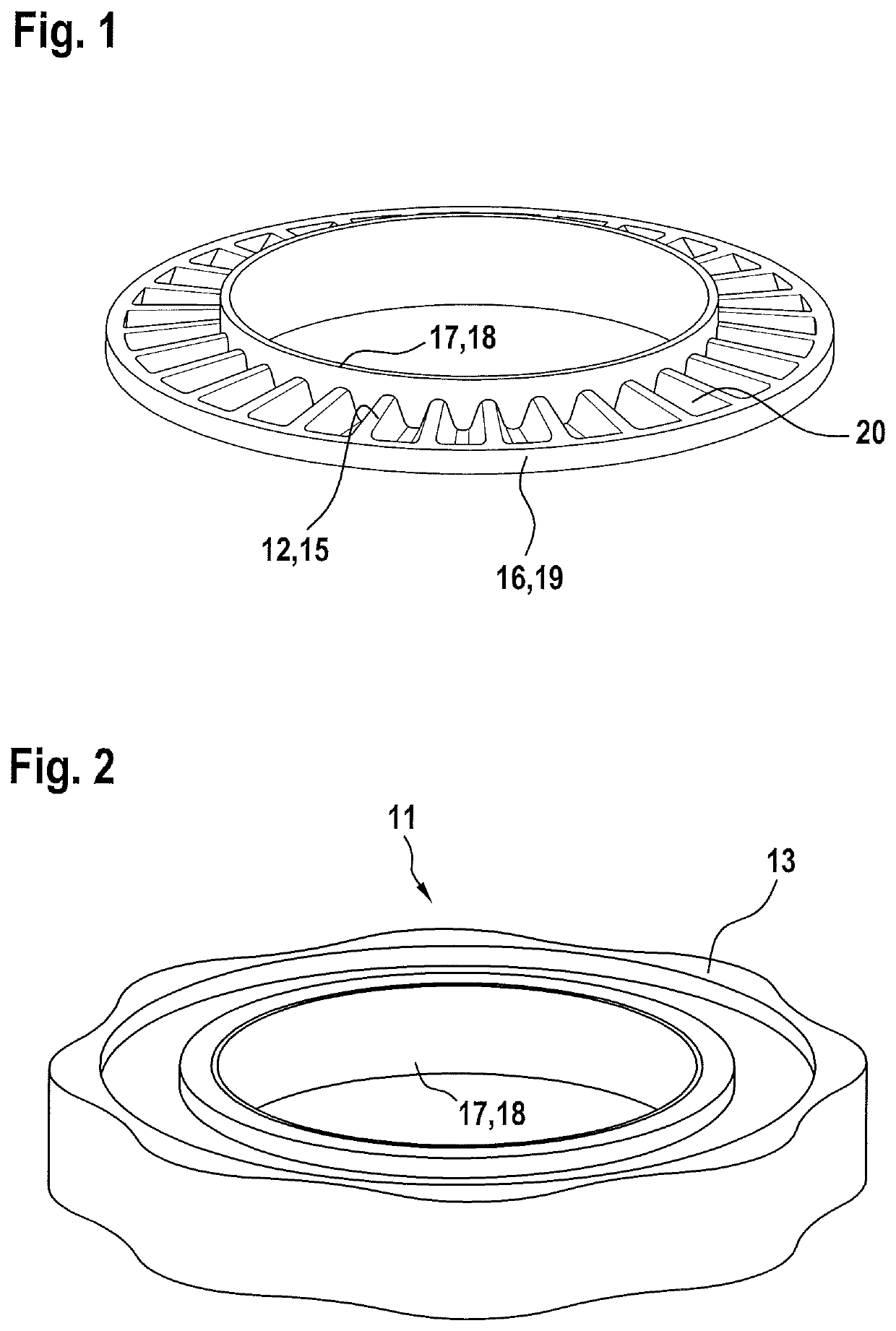
Figure 1 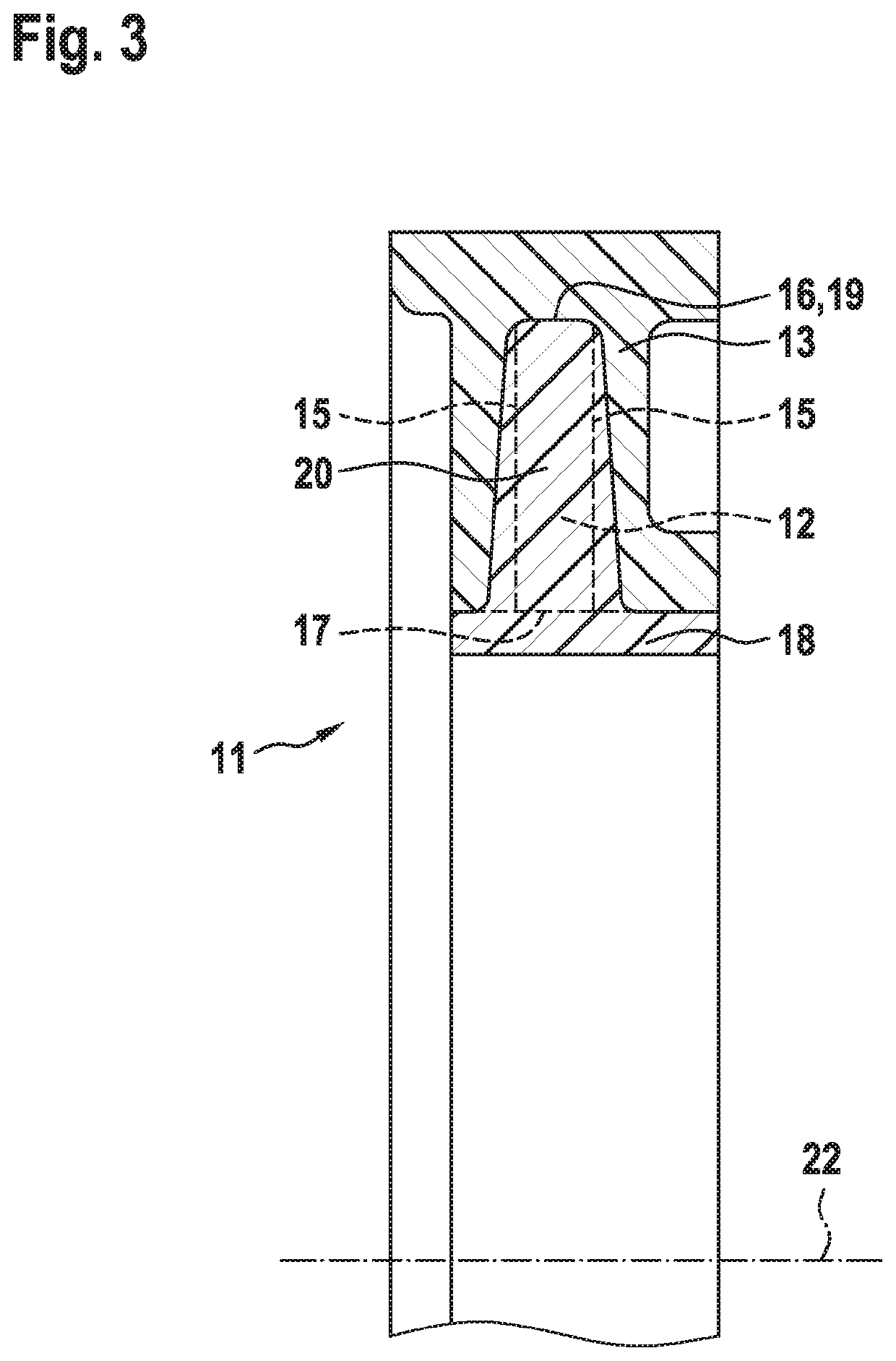
Figure 2 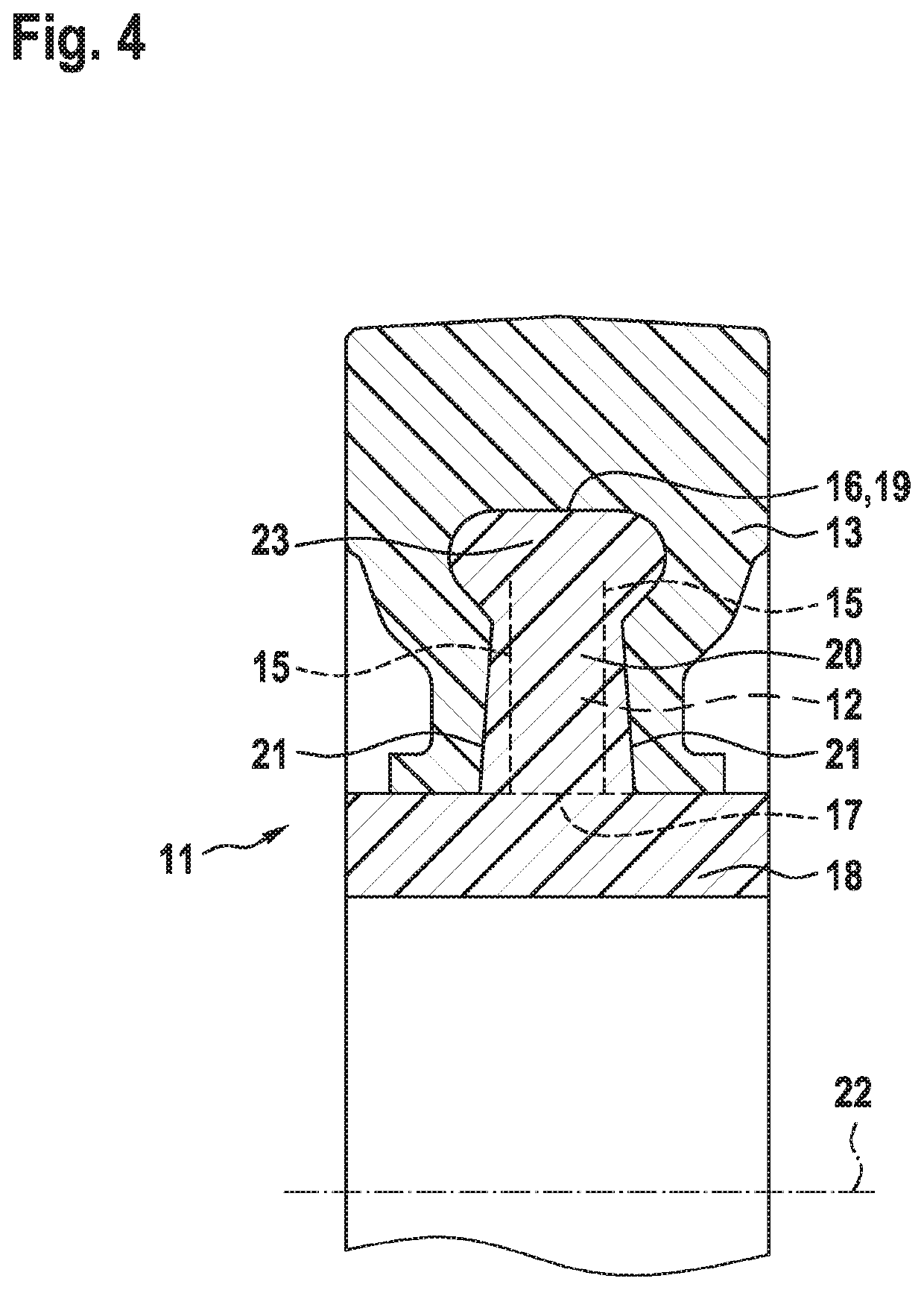
Figure 3
Abstract
Description
CROSS-REFERENCES TO RELATED APPLICATIONS
[0001] This application claims the benefit of German Application No. DE102017004617.4 filed May 13, 2017 and German Application No. DE102016012293.5 filed Oct. 16, 2016, the entire content of each of which is incorporated herein by reference.TECHNICAL FIELD
[0002] The invention relates to an overload clutch.BACKGROUND ART
[0003] A clutch of said type is known from U.S. Pat. No. 3,186,190 for the transmission of torque, in a manner protected against overloading, in a motor drivetrain. There, at the end of a shaft, the shell surface of a cylindrical metallic hub is encapsulated by a ring composed of plastic. The hub and ring are connected to one another exclusively by adhesive (static friction) action. This coupling turns to sliding friction if the rotational movement of the hub relative to the ring is braked to a critical degree. Owing to the selected material pairing, it is then the case that, under the influence of the heat of friction that arises...
Examples
Embodiment Construction
[0021]Hereinafter, embodiments according to the present disclosure will be described with reference to the accompanying drawings.
[0022]The clutch 11, which reacts reversibly and reproducibly to a predefined torque or generally to torque overload, has a substantially planar ribbed disc 12 which is produced by plastics injection moulding and which has a central hole. Said ribbed disc is, as per FIG. 3, encompassed in U-shaped fashion in axial longitudinal section, likewise by plastics injection moulding, by an encompassing ring 13, specifically is surrounded by a plastic on both of its axial side surfaces 15 and on its face 16 which runs in encircling fashion along the outer periphery 19, which plastic, as a result of intense shrinkage phenomena during the cooling process, enters into adhesive (static friction) engagement with the ribbed disc 12. The ribbed disc 12 thus acts as a hub for this rotating assembly.
[0023]Onto the inner periphery 17 of the ribbed disc 12 there is integrally...