
Connector
a technology of connecting rods and retainers, which is applied in the direction of connection, electrical apparatus, coupling device connection, etc., can solve the problems of insufficient strength of housing and retainer, and similar problems, and achieve the effect of sufficient strength and simplified insertion of retainer into the insertion hole of the housing
Patent Information
- Authority / Receiving Office
- US · United States
- Patent Type
- Applications(United States)
- Current Assignee / Owner
- Publication Date
- 2006-03-02
Smart Images
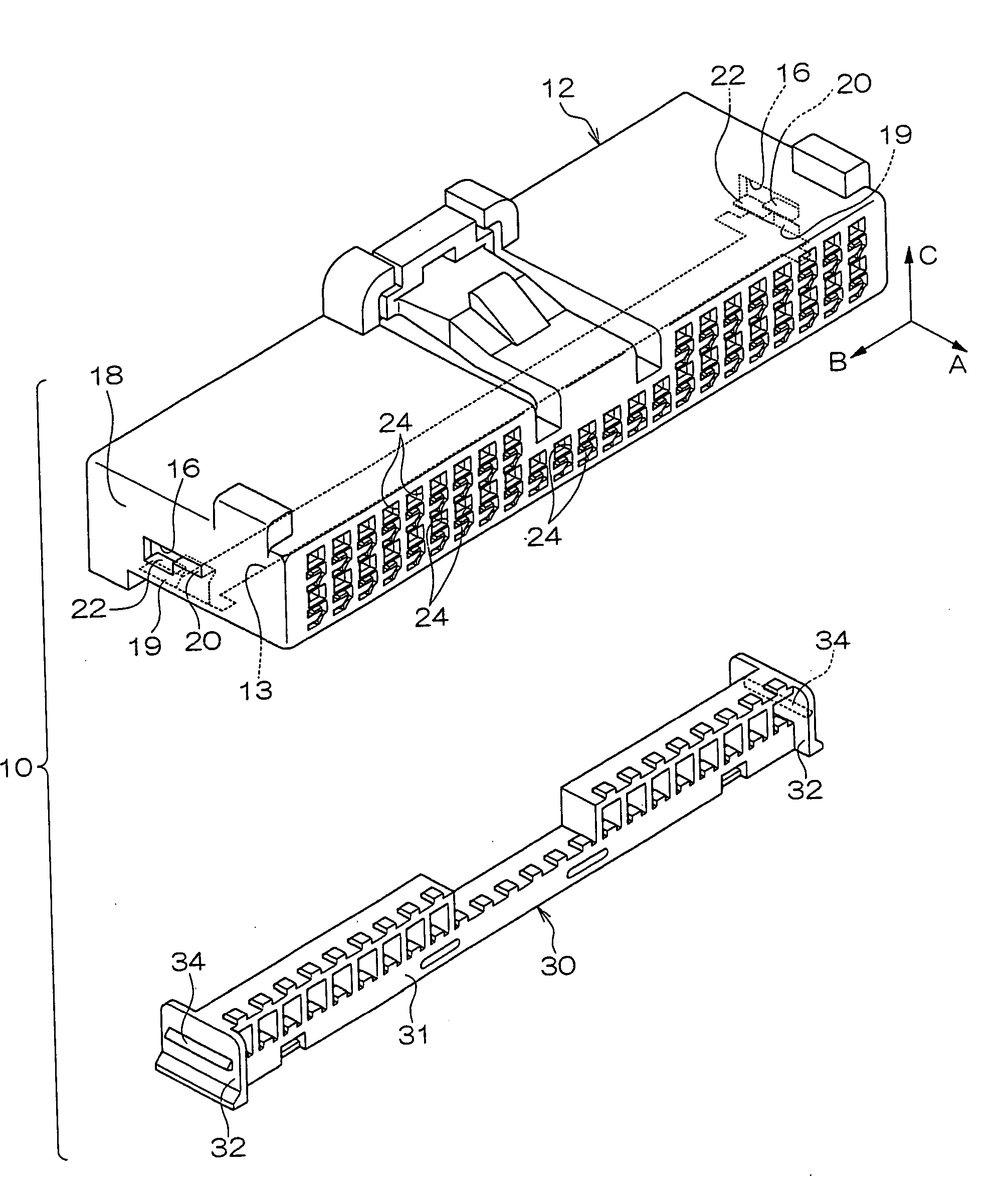
Figure 1 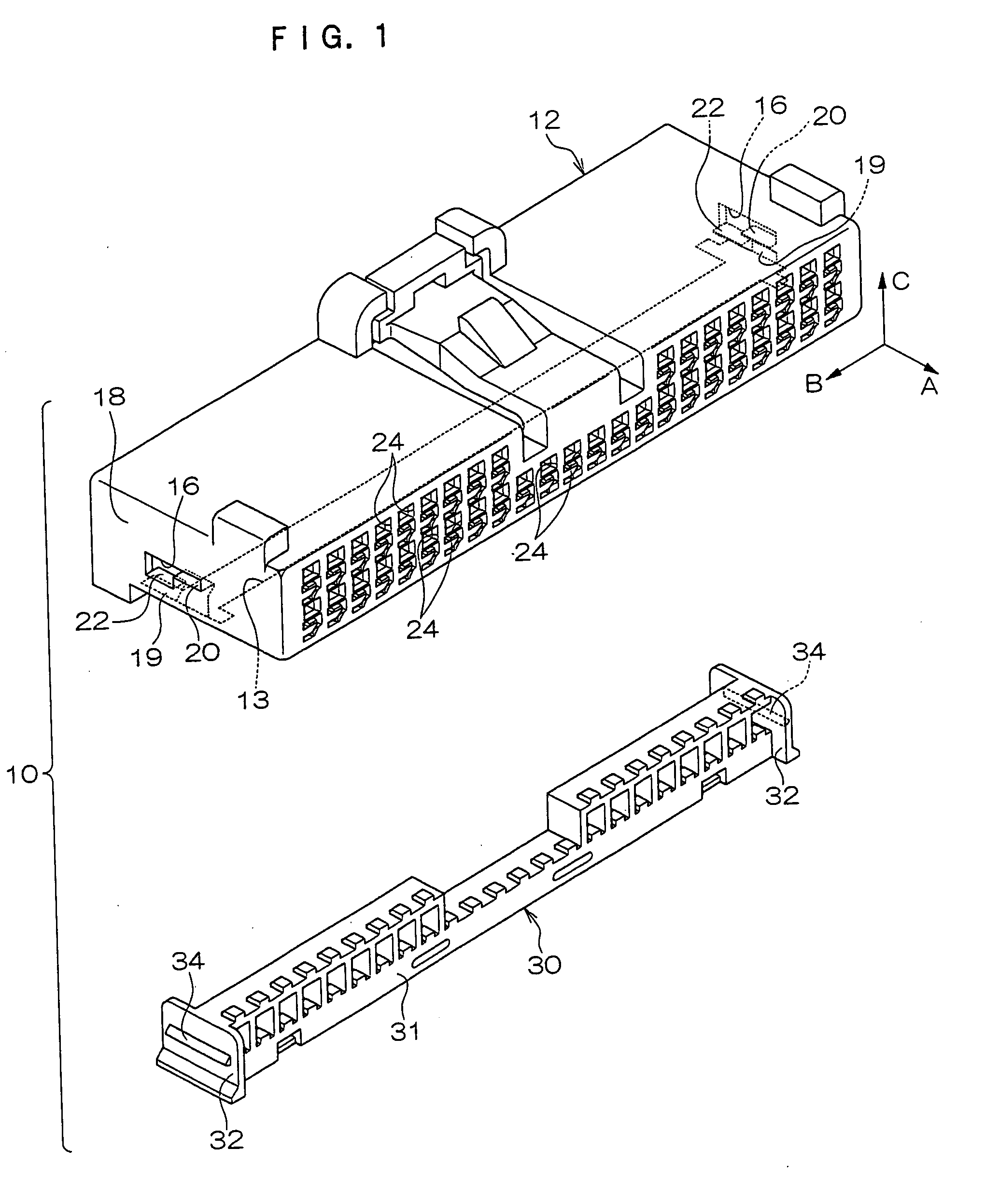
Figure 2 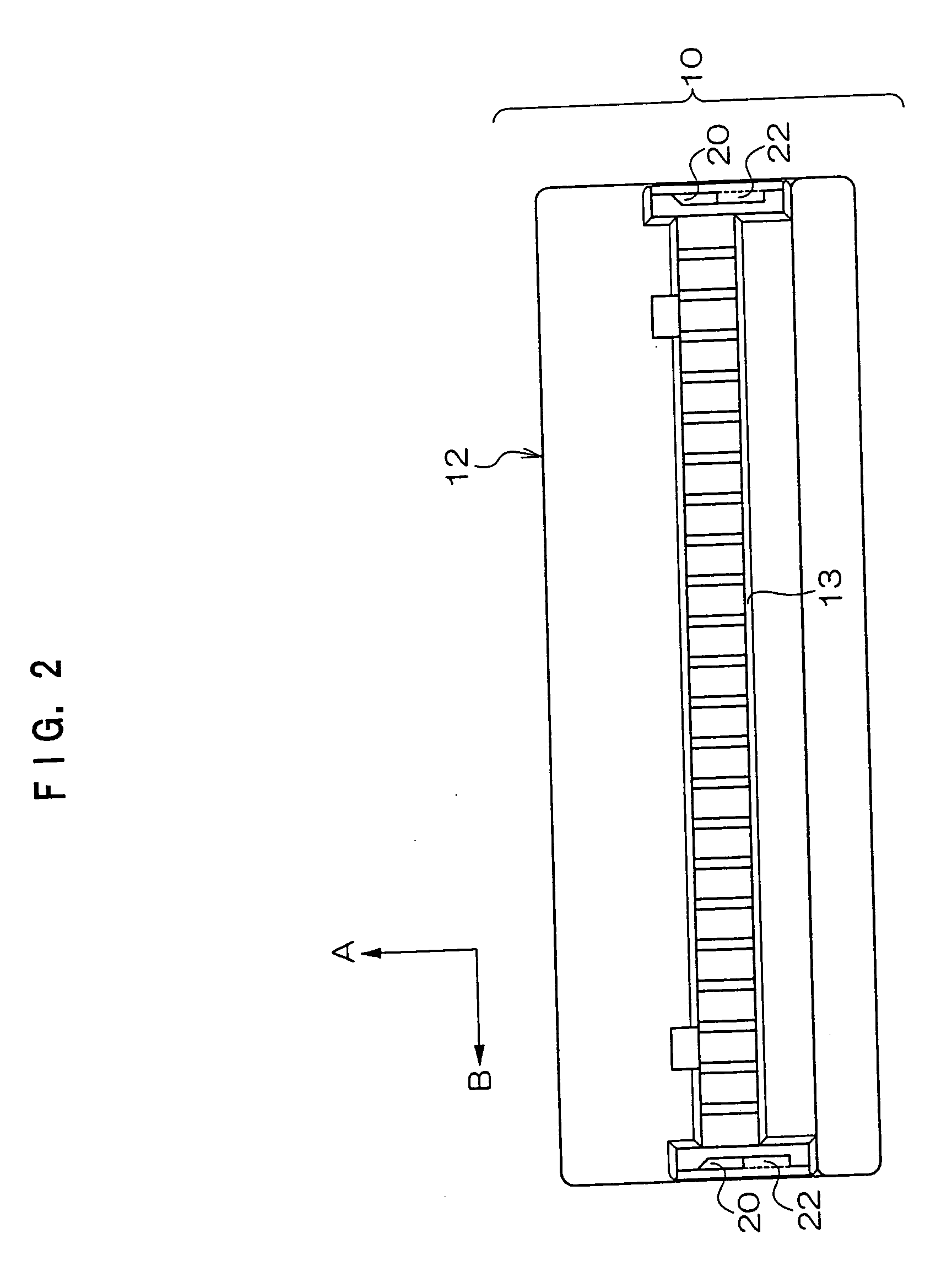
Figure 3
Abstract
Description
CROSS-REFERENCE TO RELATED APPLICATION
[0001] This application claims priority under 35 USC 119 from Japanese Patent Application No. 2004-256078, the disclosure of which is incorporated by reference herein. BACKGROUND OF THE INVENTION
[0002] 1. Field of the Invention
[0003] The present invention relates to a connector suitable for, for example, connections of wire harnesses used in vehicles and the like.
[0004] 2. Description of the Related Art
[0005] Connectors are employed for connections of, for example, wire harnesses used in vehicles and suchlike. More specifically, among such connectors, there are connectors which are provided with housings and retainers, one example of which has been disclosed in Japanese Patent Application Laid-Open (JP-A) No. 9-17484.
[0006] In this type of connector, a housing is formed in, for example, a substantially rectangular box shape, at one face of which (for example, a rear face) terminal insertion holes are plurally formed in an array, for insert...
Examples
Embodiment Construction
[0031] A connector 10 relating to an embodiment of the present invention will be described. Hereafter, for convenience of description, a direction which is shown by an arrow A where appropriate in the drawings is referred to as rearward, a direction shown by an arrow B, which intersects arrow A, is referred to as leftward, and a direction shown by an arrow C, which intersects arrow A and arrow B, is referred to as upward. FIG. 1 shows an exploded perspective view of the connector 10, and FIG. 2 shows a bottom view of a housing 12 of the connector 10. Further, FIG. 3 shows a right side view of the connector 10 according to FIG. 1, and FIG. 4 shows a cross-sectional view of the connector 10, cut along line 4-4 of FIG. 3.
[0032] As shown in FIG. 1, the connector 10 is provided with the housing 12 and a retainer 30. The housing 12 of the connector 10 is constituted of a resin material and is formed in a substantially rectangular box shape. Terminal insertion holes 24, for insertion of u...