
Automatic pipette identification and detipping
a technology of automatic identification and pipette, applied in the field of pipettes, can solve the problems of preventing accurate fluid aspiration and dispensing, difficult to remove all contaminants, and expensive and time-consuming tip washing, and achieve the effects of facilitating the removal of the tip
Patent Information
- Authority / Receiving Office
- US · United States
- Patent Type
- Applications(United States)
- Current Assignee / Owner
- Publication Date
- 2006-05-18
- Estimated Expiration
- Not applicable · inactive patent
Smart Images
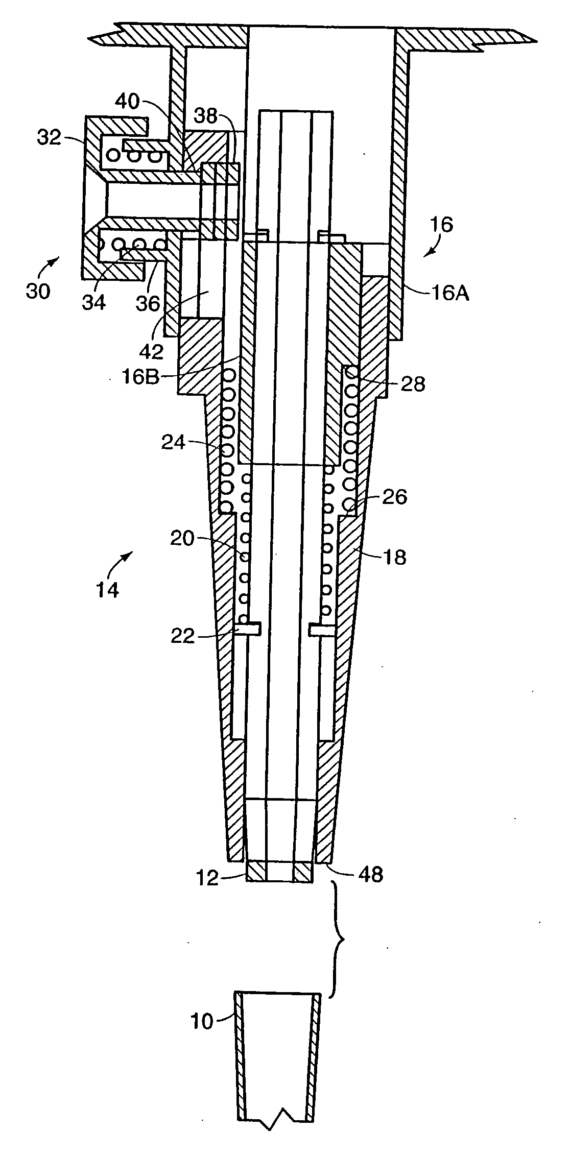
Figure 1 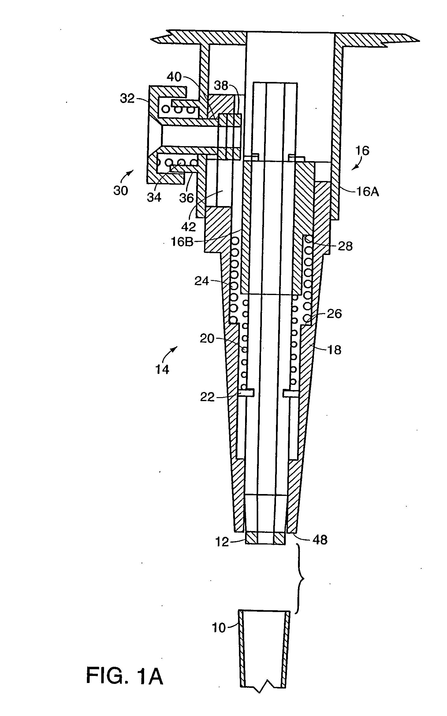
Figure 2 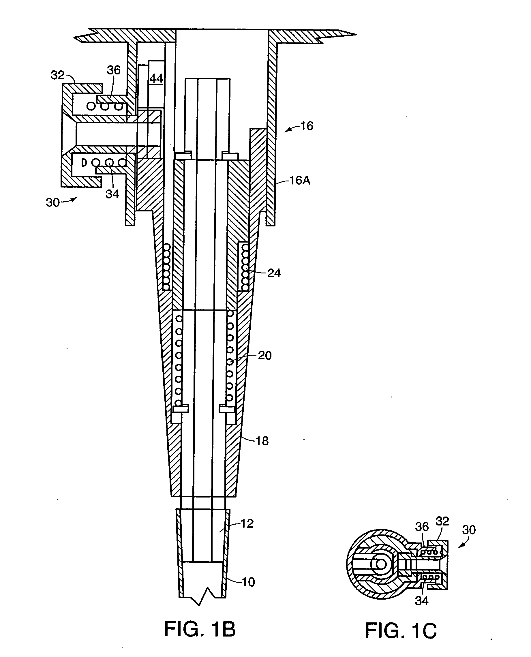
Figure 3
Abstract
Description
RELATED APPLICATIONS
[0001] This application is a continuation of U.S. patent application Ser. No. 10 / 612,252, filed Jul. 1, 2003, which is a division of U.S. patent application Ser. No. 09 / 873,842, filed Jun. 4, 2001, which claims priority from U.S. provisional application Ser. No. 60 / 214,206 filed Jun. 26, 2000.FIELD OF THE INVENTION
[0002] This invention relates to pipettes, and more particularly to pipettes having automatic mechanisms for identifying and / or removing tips. BACKGROUND OF THE INVENTION
[0003] Pipettes are commonly utilized to aspirate a fluid from one container or other source and to dispense the fluid to a second container or other receptacle. Since the fluid being aspirated and dispensed is frequently analyzed or otherwise tested after being dispensed, and in order for such testing or analysis to be accurate, it is important that a sample not be contaminated by fluid from a prior aspirated sample. While it is possible to wash a pipette tip between aspirations in ...
Examples
Embodiment Construction
[0021] Referring to FIGS. 1A-1C, a first embodiment of the invention is shown wherein a tip 10 is mounted to a nozzle 12 which is part of a nozzle assembly 14. Assembly 14 includes a housing 16 having an outer sleeve 16A and an inner sleeve 16B. An ejector sleeve 18 surrounds nozzle 12, extending to a point near the distal end of the nozzle to which tip 10 is mounted, and fits at its proximal end between sleeves 16A and 16B of housing 16. Nozzle 12 is spring biased to the released position shown in FIG. 1A by a compression spring 20 extending between ring 22 fixed to nozzle 12 and the end of housing sleeve 16B. Ejector sleeve 18 is also spring biased to the released position of FIG. 1A by a compression spring 24 extending between an interior shoulder 26 of sleeve 18 and a shoulder 28 on inner housing sleeve 16B. In order for nozzle 12 to be movable as discussed herein, a flexible connection, for example a flexible hose, should be provided connecting the nozzle to its drive piston or...