
Storm panel mounting assembly
Patent Information
- Authority / Receiving Office
- US · United States
- Current Assignee / Owner
- Publication Date
- 2007-01-04
- Estimated Expiration
- Not applicable · inactive patent
Smart Images
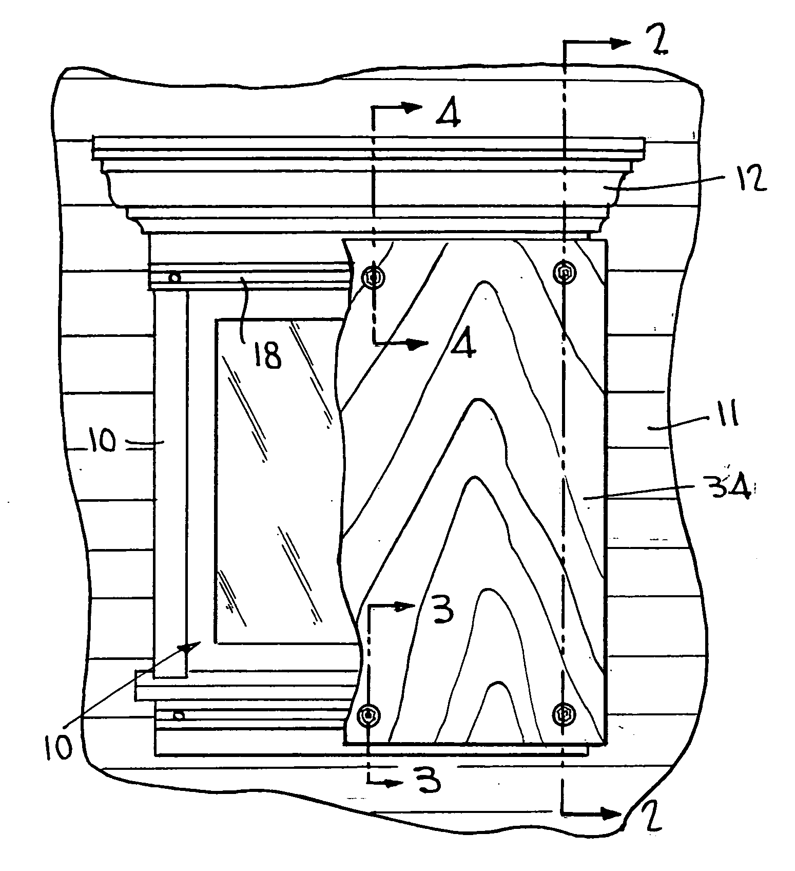
Figure 1 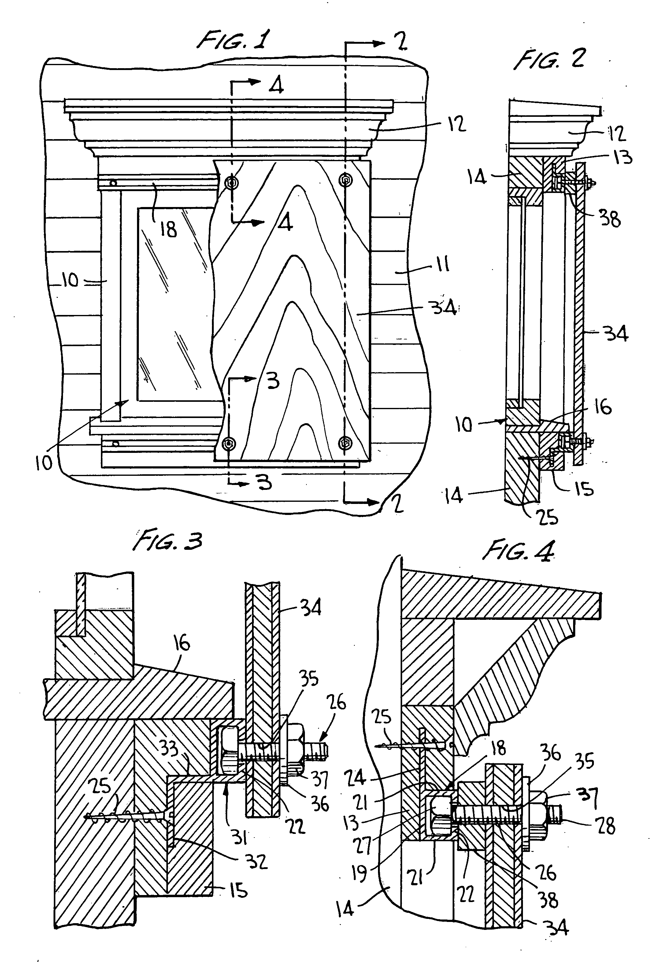
Figure 2 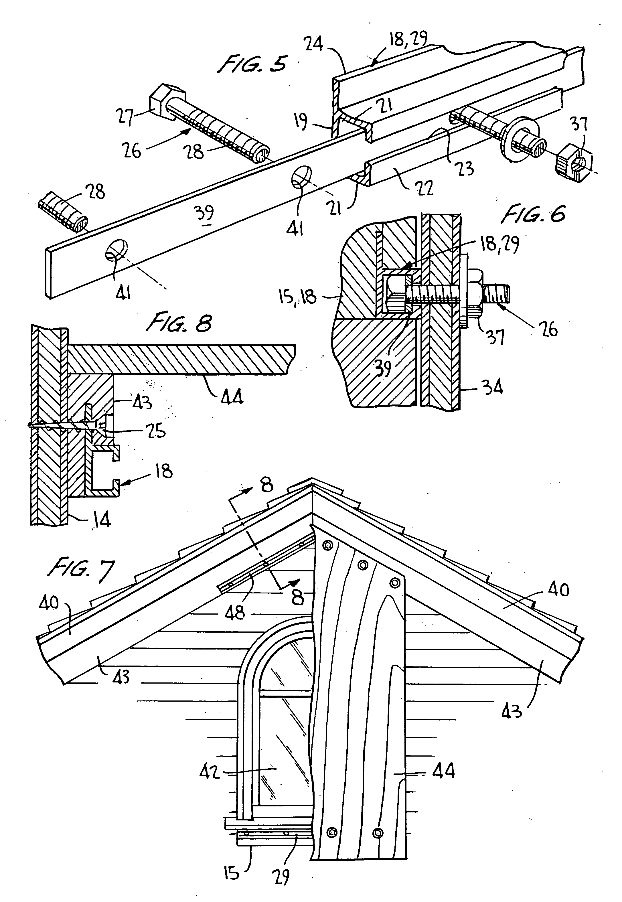
Figure 3
Abstract
Description
RELATED APPLICATION
[0001] Priority is claimed based on provisional application No. 60 / 695,432, filed Jul. 1, 2005.BACKGROUND OF THE INVENTION
[0002] This invention relates generally to an assembly for mounting storm panels over glass openings such as window and door structures of a building structure, and more particularly to such an assembly having elongated channel members for supporting bolts utilized to quickly mount the storm panels in place, the channels being integrated with the window / door trim members mounted on the building structure at least above and below the window / door structures.
[0003] Storm panels are typically provided for protecting glass openings of a building structure, such as windows, entry doors, sliding glass doors, etc., from damage which may result from high winds and flying debris experienced during storms such as a tropical depression or hurricane. The storm panels are typically mounted using threaded fasteners or nails driven directly through the sidi...
Examples
Embodiment Construction
[0019] Turning now to the drawings wherein like reference characters refer to like and corresponding parts throughout the several views, a window structure 10 is shown as part of a building structure such as a house having siding 11 and which may have window molding 12. As shown in more detail in FIGS. 2, 3, and 4, an upper trim member 13 is, as typical, mounted on the face of building structure 14 itself, and a lower trim member 15 is mounted below sill member 16 likewise directly to building structure 14. Side trim members, one of which is shown at 17 in FIG. 1, likewise may surround the window or door structure.
[0020] In accordance with the invention, upper trim member 13 incorporates an elongated channel member 18, one embodiment of which is seen more clearly in FIGS. 4 and 5, as comprising a back wall 19, side walls 21, and a front wall 22. The front wall has an elongated open slot 23 extending lengthwise of the channel member, and a transverse support plate or flange 24 may f...