
Electrical connector
a technology of electrical connectors and connectors, applied in the field of electrical connectors, can solve the problems of reducing the strength reducing and undesirable situations, so as to facilitate the mounting of the key, reduce the exposure of the interior parts of the connector, and improve the resistance of the coding key to for
Patent Information
- Authority / Receiving Office
- US · United States
- Patent Type
- Applications(United States)
- Current Assignee / Owner
- Publication Date
- 2010-04-08
Smart Images
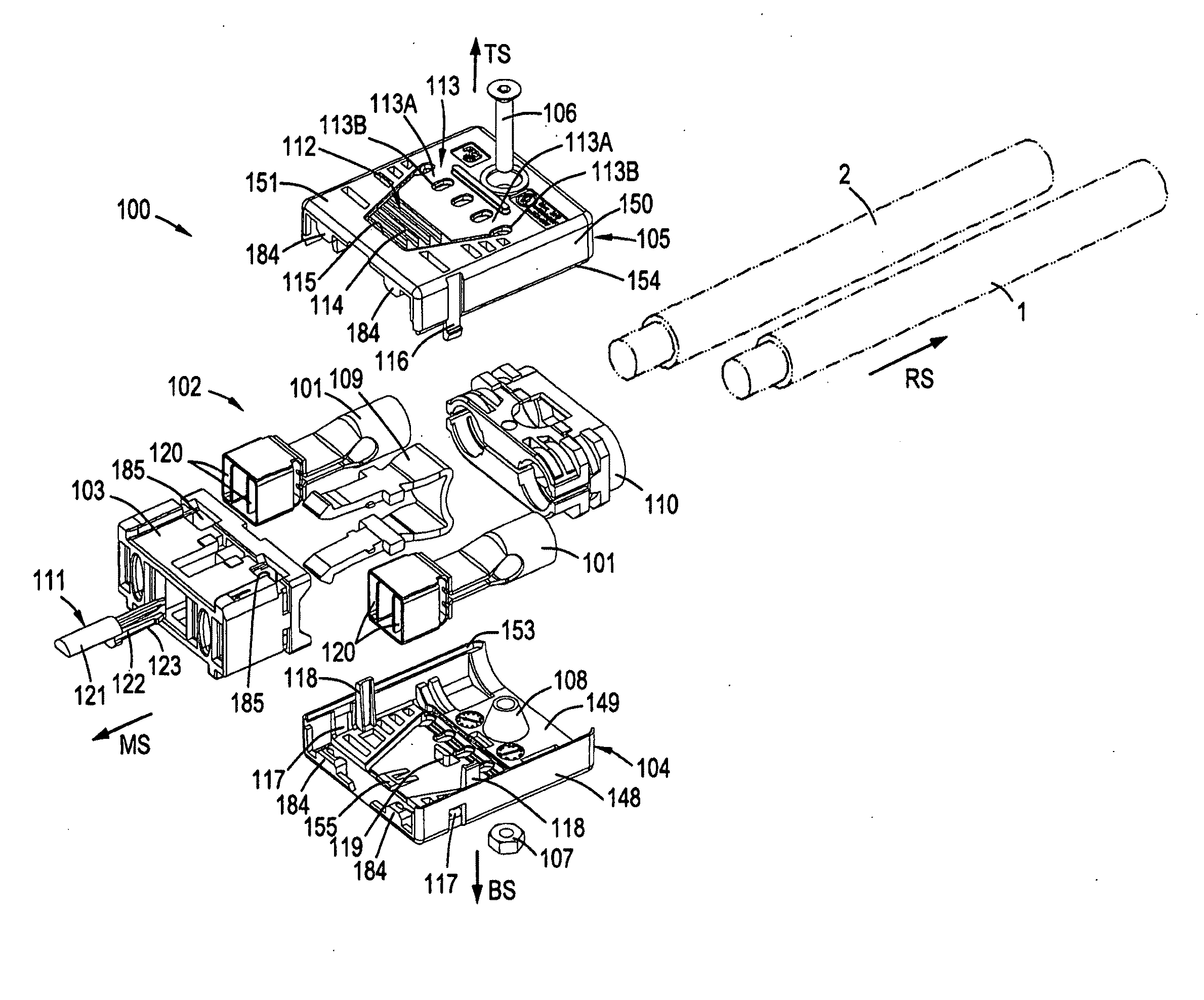
Figure 1 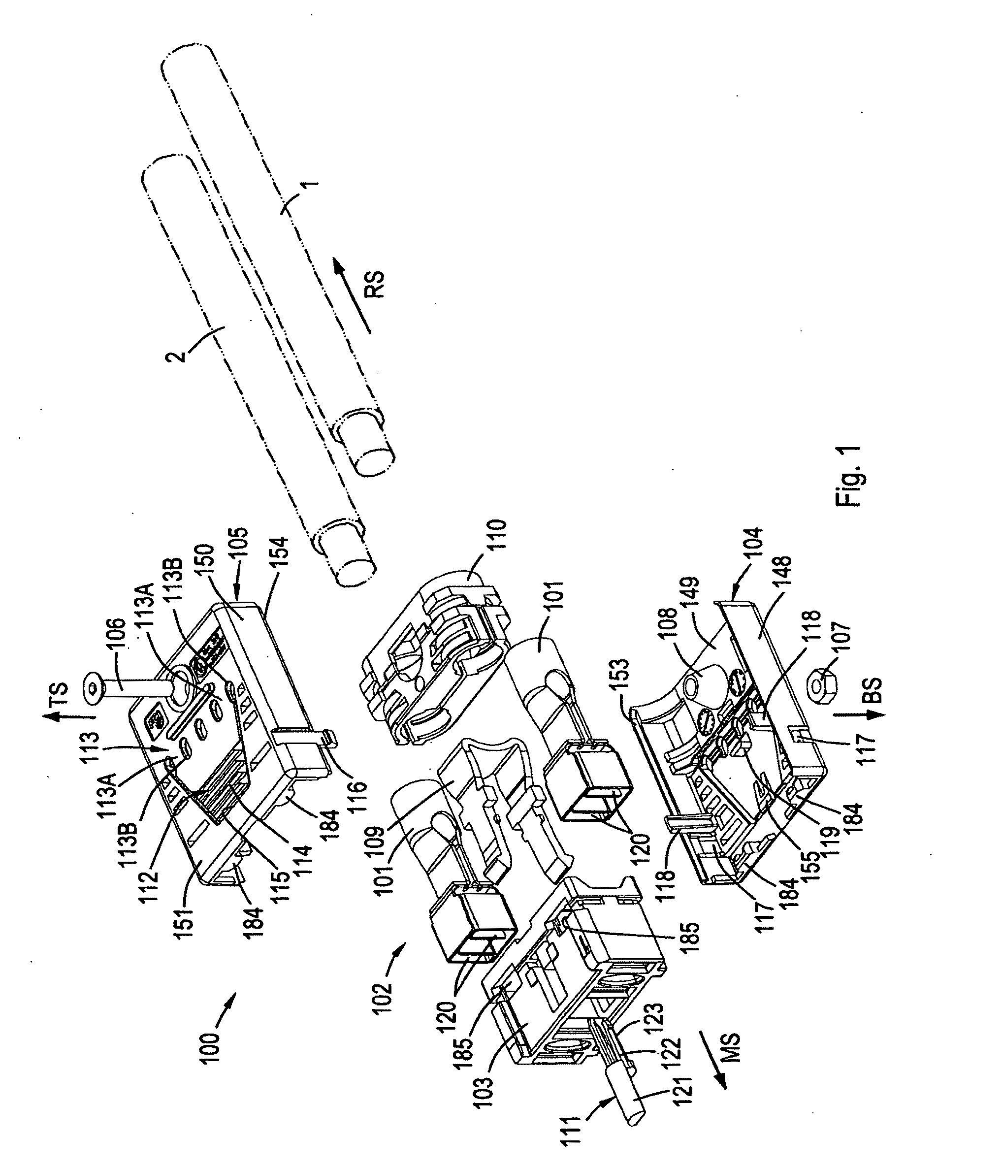
Figure 2 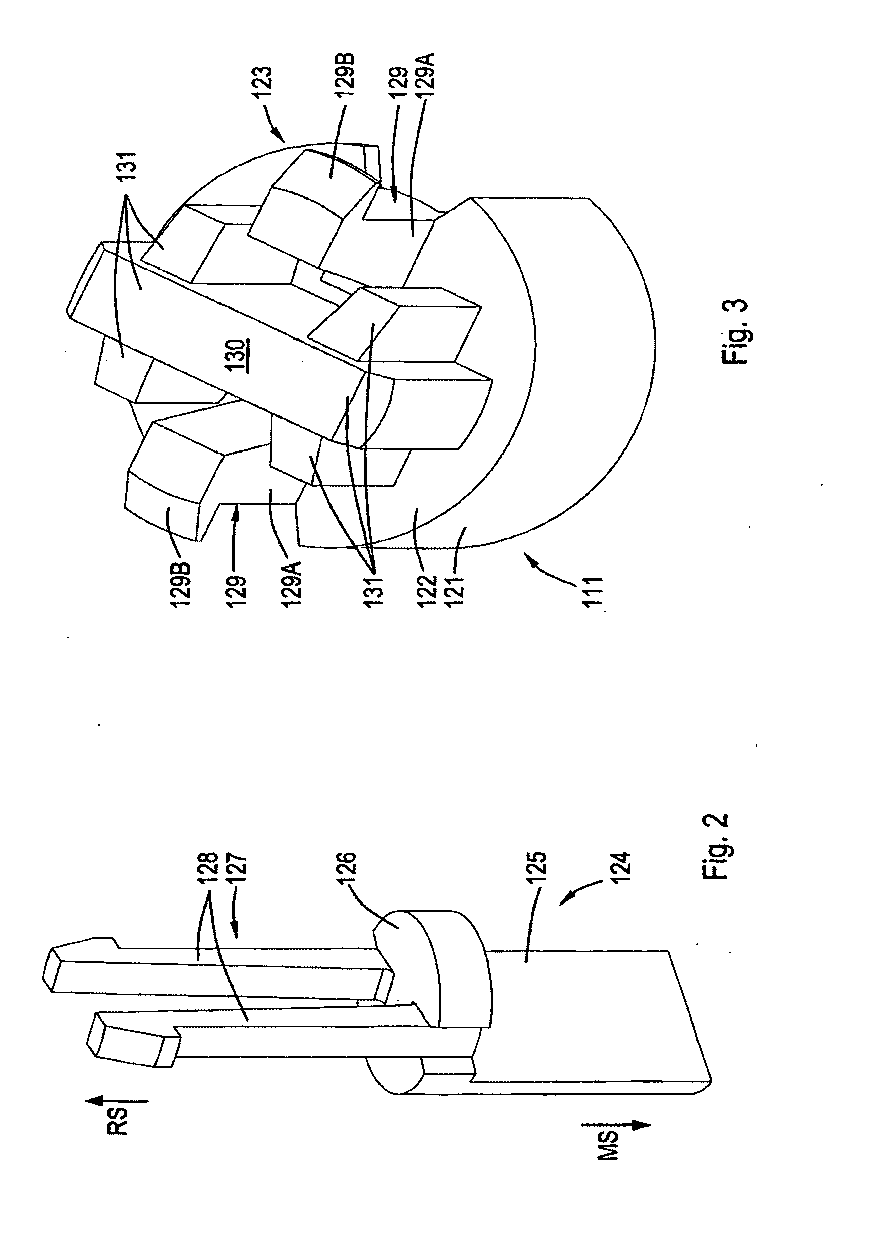
Figure 3
Abstract
Description
FIELD OF THE INVENTION
[0001] The present invention relates to the field of connectors, in particular to electrical connectors. More specifically, the invention relates to the field of safety and robustness of such connectors.BACKGROUND OF THE INVENTION
[0002] The use of a connector and a counterpart, such as a board connector, is widely known for power supply purposes and / or signal transfer. Typically, connectors may comprise a plurality of contacts.
[0003] Relatively large forces may be exerted to connectors in a mated situation and / or during the operation of mating, e.g. mating with a relative angling motion. This is especially the case for cable connectors, since the weight of cables may exert a pulling force, possibly with a torsional pulling effect, on a connector. Such (un-) mating or accidental forces may damage or break (one or more portions of) a connector, and thus may lead to undesired, possibly dangerous, situations.
[0004] In addition, connectors generally comprise a pair of h...
Examples
Embodiment Construction
[0101]Referring to FIG. 1, there is shown an exploded perspective view of an electrical connector 100 incorporating features of the invention. Although the invention will be described with reference to the exemplary embodiments shown in the drawings, it should be understood that the invention can be embodied in many alternate forms of embodiments. In addition, any suitable size, shape or type of elements or materials could be used. Further, elements and / or aspects discussed with respect to one embodiment may be suitably combined with those of another embodiment.
[0102]FIG. 1 shows a straight cable plug connector 100, adapted for mating with a receptacle mating connector such as the board connector 200 discussed below with respect to, e.g., FIGS. 13 and 28. The connector 100 generally has a front side or mating side MS, a rear side RS, a top side TS and a bottom side BS, the directions being indicated with arrows.
[0103]In the following, substantially corresponding or identical parts a...