
Protective element and secondary battery device
a secondary battery and protection element technology, applied in the field of protection element and secondary battery device, can solve the problems of increasing material cost, low degree of discharge of this type, and long time taken until the blowout of the conductor reliably occurs, so as to prevent uneven distribution of the degree of discharge, reduce environmental burden, and reduce the effect of dispersion
Patent Information
- Authority / Receiving Office
- US · United States
- Patent Type
- Applications(United States)
- Current Assignee / Owner
- Publication Date
- 2011-01-20
Smart Images
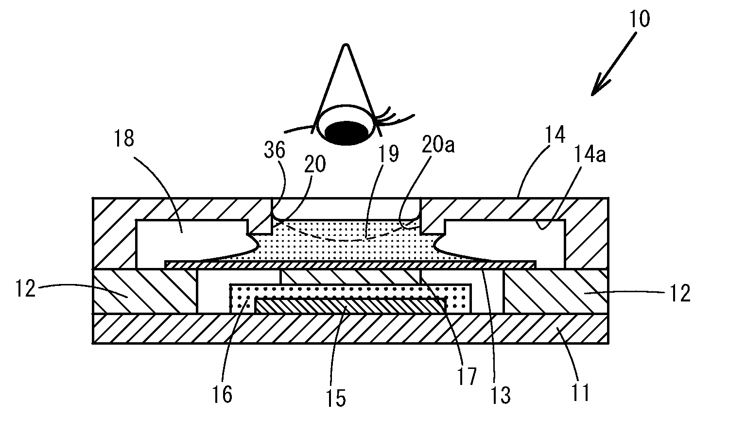
Figure 1 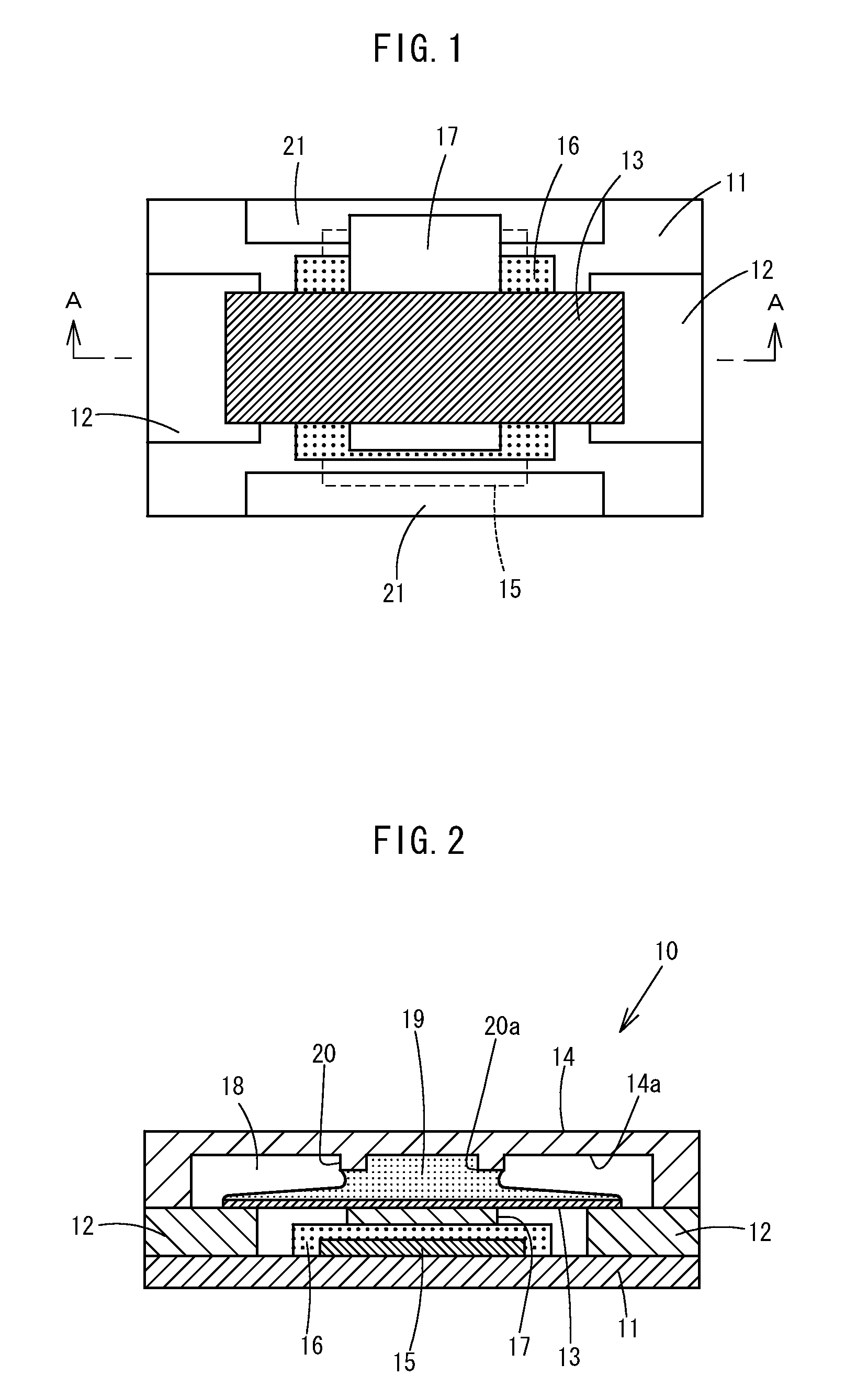
Figure 2 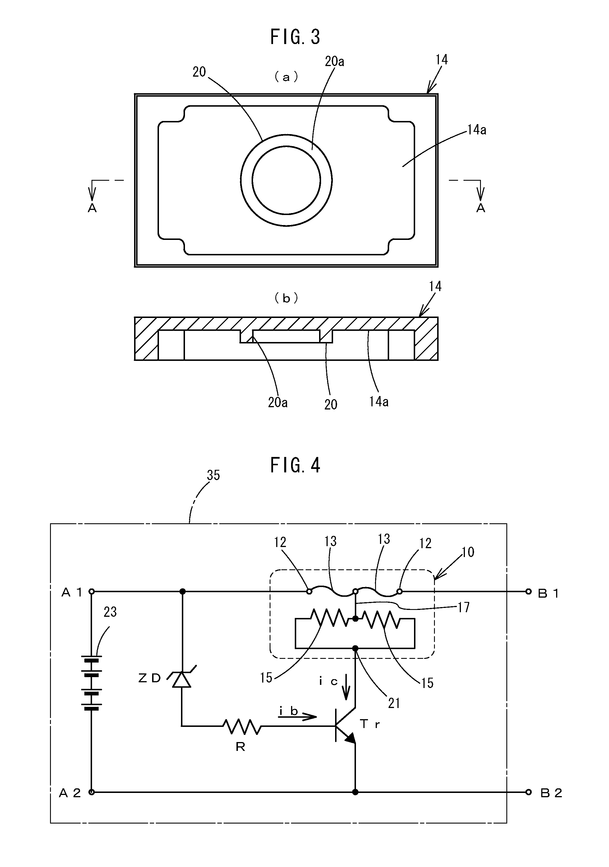
Figure 3
Abstract
Description
TECHNICAL FIELD
[0001] This invention relates to a protection element and a secondary battery device employing the protection element for, in case that an overcurrent or overvoltage is applied, allowing a soluble conductor to cause a blowout due to a heat of such overcurrent or overvoltage, thereby shutting off a current.BACKGROUND ART
[0002] Conventionally, a protection element mounted on a secondary battery device or the like is employed as the one having a function of protection from an overvoltage as well as an overcurrent. This protection element is formed so that: a heating element and a soluble conductor made of a low-melting metal are laminated on a board; and the soluble conductor causes a blowout due to an overcurrent, and if an overvoltage occurs as well, power is supplied to the heating element in the protection element, and the soluble conductor causes a blowout due to a heat of the heating element. The blowout of the soluble conductor is due to the goodness of wettability ...
Examples
example 1
[0096]Next, an example of the protection element of this invention and an operating circuit of a secondary battery device employing the element will be described below. In this example, experiments were carried out by constituting a circuit similar to a power circuit employed in an actual secondary battery device. As to a protection element of a conventional structure, shown in FIG. 28, and a protection element having a cylindrical protrusive stripe on the abovementioned insulation cover member of the first embodiment, comparative experiment of their operation was carried out.
[0097]A protrusion height of the protrusive stripe meets a condition of Formula 1.
B−A≧C (1)
wherein: A denotes a protrusion quantity of a protrusive stripe 20 from an inside top face of an insulation cover member 14; B denotes an interval between a baseboard 11 and the inside top face of the insulation cover member 14; and C denotes a height after blowout of a soluble conductor 13 from the baseboard 11.
[0098]A ...
example 2
[0101]Similarly, table 2 shows results obtained by relatively comparing rates of a blowout time of a structure according to a second embodiment of the invention (the invention 2) while each of MAX, MIN, AVE, and 3σ was defined to be 100%, as to the blowout time of a soluble conductor, in a conventional cover plate structure. A height of a protrusive stripe is equal to that of Example 1. Experiments were carried out at the time of low-power operation of 6 W and at high-power operation of 35 W, and 50 elements were employed in each of the experiments. As a flux, the halogen-containing one was employed.
[0102]In the experimental results as well, a MAX operating time was reduced by 14% at low power, and dispersion (3σ) was reduced by 45%.
TABLE 2Relative comparison of experimental results (N = 50 pcs)Low powerHigh powerPower applied to heating resistor6 W35 WStructure of insulation cover plateTheThePriorinven-Priorinven-arttion 2arttion 2BlowoutMAX100%86%100% 93%time ofMIN100%98%100%106%s...
example 3
[0103]Similarly, table 3 shows results obtained by relatively comparing rates of a blowout time with one another as to the protection elements having had the structure of the protrusive stripe of the first embodiment of the invention (the invention 1) and the structure shown in FIG. 9 of the above-described embodiments while each of MAX, MIN, AVE, and 3σ was defined to be 100%, as to the blowout time of a soluble conductor, in a conventional cover plate structure. Experiments were carried out at low-power operation of 6 W, and 20 elements were employed in each of the experiments. As a flux, the halogen-free one was employed.
[0104]In the experiments, dispersion (3σ) of the blowout time, in a structure in which a protrusive stripe had been provided, became lesser in comparison with that in the conventional structure. In addition, as to the shape of the protrusive stripe, a structure of a cylindrical shape of the first embodiment (the invention 1) showed good results in items of MAX, M...