
A fitness equipment spring counterweights banlancer
a technology of counterweights and springs, applied in the field of fitness equipment, can solve the problems of unfavorable widespread popularity, high transportation costs, and high cost, and achieve the effect of reducing equipment investment and labor load, and favorable production conditions
Patent Information
- Authority / Receiving Office
- US · United States
- Current Assignee / Owner
- Publication Date
- 2016-11-17
- Estimated Expiration
- Not applicable · inactive patent
Smart Images
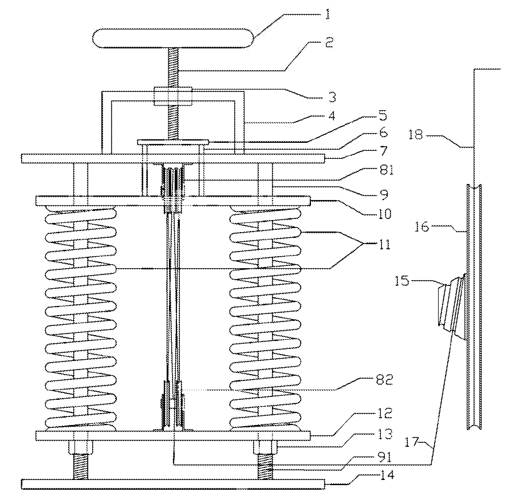
Figure 1 
Figure 2
Abstract
Description
TECHNICAL FIELD
[0001] The invention is related to a fitness equipment, particularly relating to a fitness equipment counterweights device.BACKGROUND
[0002] Most of existing counterweights devices are using counterweights as the load. Due to the configuration of counterweights being affected by the space, the direction, the cost and many other factors, and thus there are disadvantages of a huge volume, a high cost, and a high transportation cost, which is unfavorable for the widespread popularity. For example, counterweights portion of the traditional fitness equipment is usually made up of multiple counterweights. The design can only be carried out by way of laminating, and the gravity is adjusted by increasing or decreasing the number of the counterweights. Thus, the height and the adjustment precision of the gravity of the fitness equipment are limited, easily leading to a problem, i.e., it is heavier with one more counterweight while it is lighter with one less counterweight. It is ...
Examples
Embodiment Construction
[0024]As shown in FIG. 1, the embodiment has hand wheel 1, lead screw 2, framework connecting nut 3, gravity scale indicating device frame 4 (a way of scale indication is used in this embodiment), plane press plate 5, plane press plate guiding pillar 6, upper frame beam 7, upper pulley block 81, lower pulley block 82, spring guiding pillar 9, upper spring seats 10, two springs 11, lower spring seat 12, spring guiding pillar connecting nut 13, lower frame beam 14, vortex track 15, big wheel 16, steel wire rope connecting the pulley block and the vortex track 17, steel wire rope connecting the big wheel and fitness equipment 18.
[0025]Hand wheel 1 is fixed at the top of lead screw 2. Two springs 11 are arranged between the upper spring seat 10 and the lower spring seat 12. After going through two springs 11 and upper spring seat 10 and lower spring seat 12, two ends of spring guiding pillar 9 are connected to upper frame beam 7 and lower frame beam 14 respectively, to form foundation f...