
Clamp apparatus
a technology of clamping and clamping rods, which is applied in the direction of clamps, work holders, manufacturing tools, etc., can solve the problem of not being able to take out workpieces from the clamping rods, etc., and achieve the effect of convenient and reliable releas
Patent Information
- Authority / Receiving Office
- US · United States
- Current Assignee / Owner
- Publication Date
- 2016-12-08
- Estimated Expiration
- Not applicable · inactive patent
Smart Images
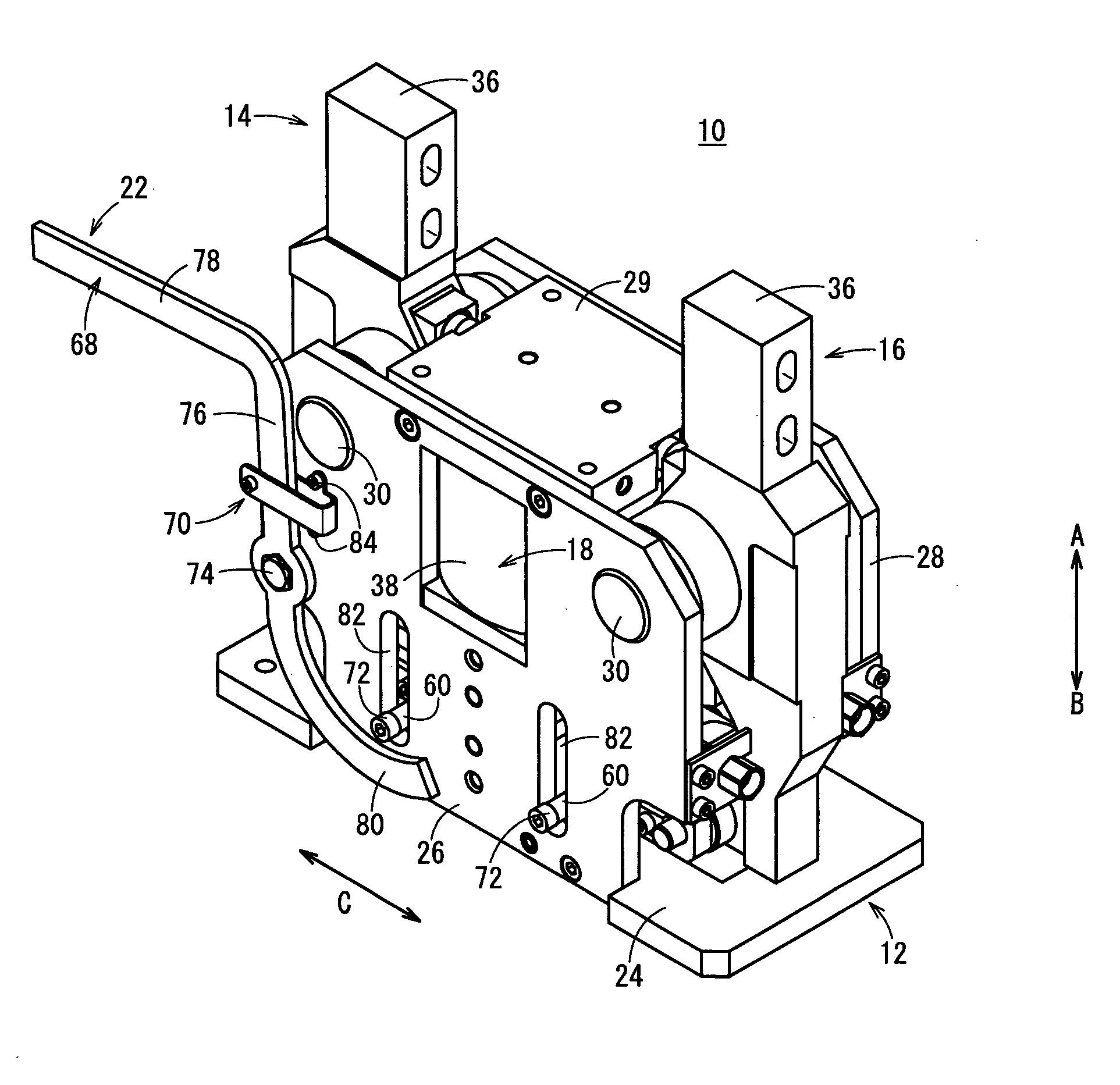
Figure 1 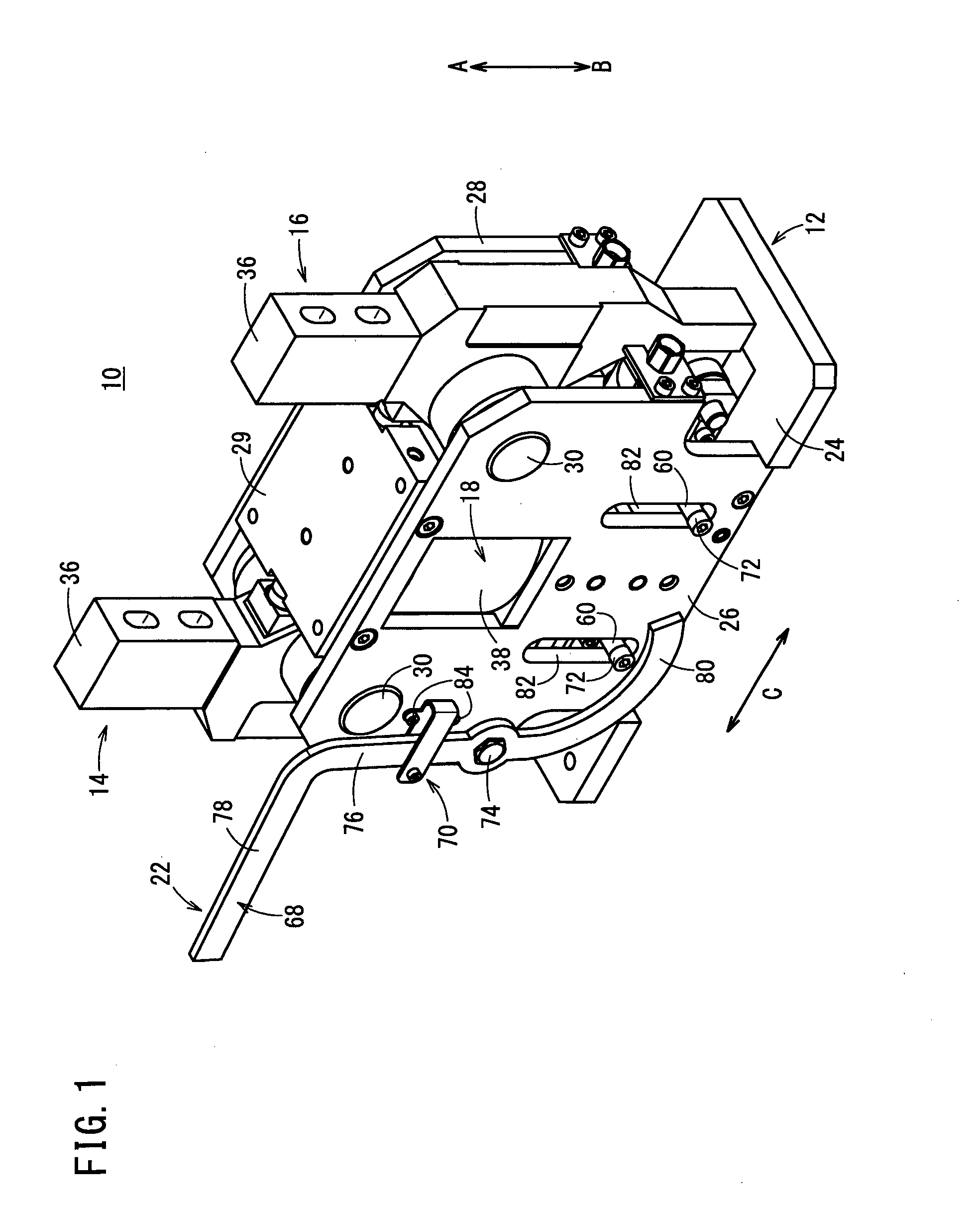
Figure 2 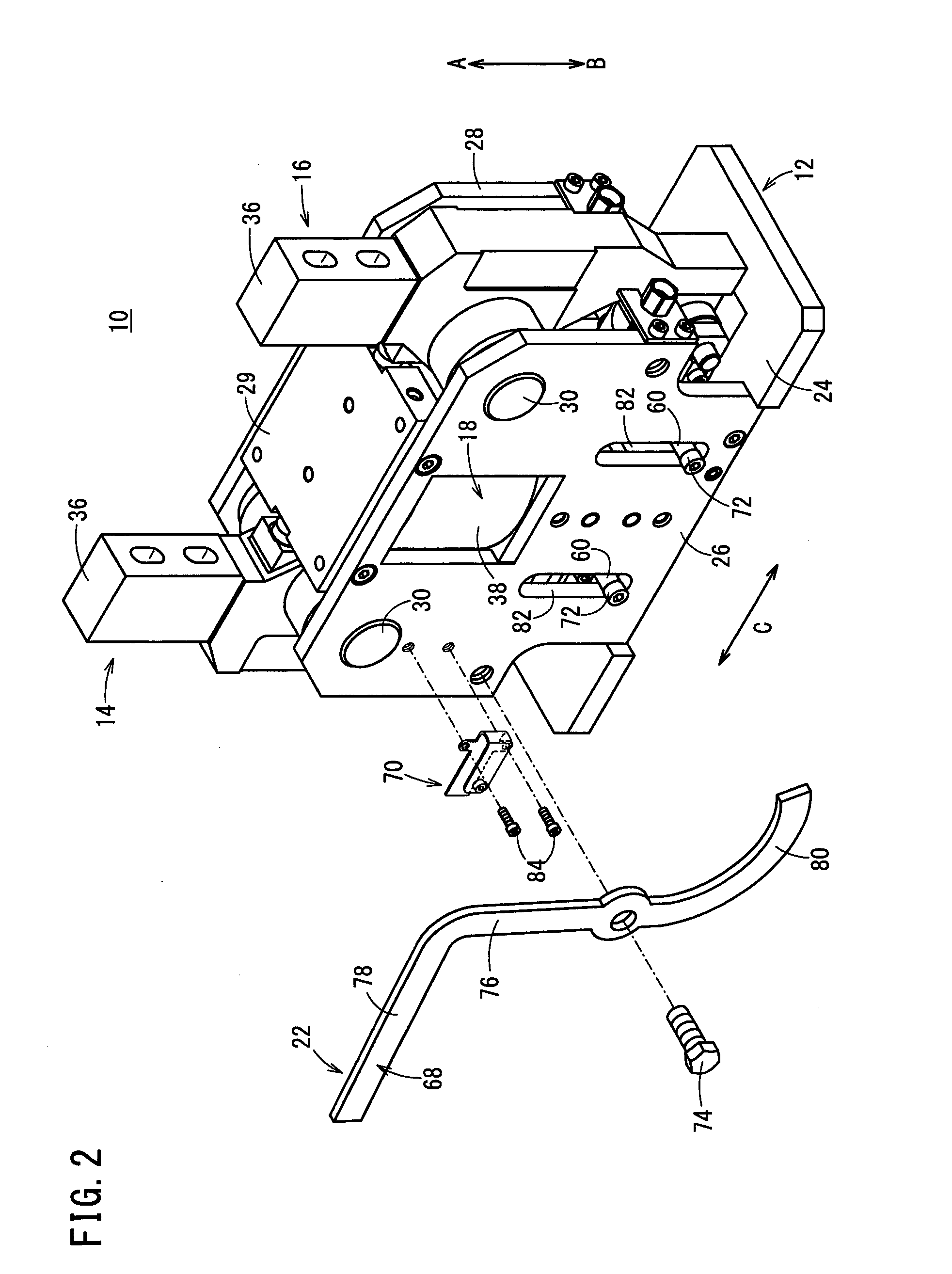
Figure 3
Abstract
Description
TECHNICAL FIELD
[0001] The present invention relates to a clamp apparatus for clamping workpieces on an automated assembly line or the like.BACKGROUND ART
[0002] Heretofore, for example, in an automated assembly line for automobiles, an assembly process has been performed in which clamping is carried out by a clamp apparatus under a condition in which pre-formed frames are positioned in an overlaid manner and the frames are welded together.
[0003] In one such clamp apparatus, as disclosed in Japanese Patent No. 4950123, a pair of two clamp arms are provided respectively on left and right sides, the clamp arms being disposed for rotation respectively through pins. Further, proximal ends of the clamp arms are supported pivotally via a base which is connected to a drive unit, whereby distal ends of the clamp arms are operated to open and close. Thus, a workpiece such as a frame or the like is gripped from the left and right by the distal ends of the pair of clamp arms.SUMMARY OF INVENTION[00...
Examples
Embodiment Construction
[0022]As shown in FIGS. 1 through 7, a clamp apparatus 10 includes a body 12, a pair of first and second clamp arms 14, 16 pivotally supported rotatably on the body 12, a drive unit 18 fixed to the body 12, a driving force transmission mechanism 20 that transmits driving forces of the drive unit 18 to the first and second clamp arms 14, 16, and a manual release mechanism 22, which is capable of forcibly releasing, by manual operation, the clamped state of a workpiece W that is clamped by the first and second clamp arms 14, 16.
[0023]The body 12, for example, is made up from a base 24, which is formed in a planar shape and is arranged in a horizontal direction, and a pair of first and second plate bodies 26, 28, which are connected respectively to both side surfaces of the base 24, and which are separated mutually by a predetermined distance. The first and second plate bodies 26, 28 are perpendicular to the base 24, and are formed at predetermined heights in an upward direction (the d...