
Magnetic disc apparatus and magnetic head in which a recording/reproduction element is mounted on a slider via a piezoelectric element
a piezoelectric element and magnetic disc technology, applied in the direction of manufacturing head surfaces, recording information storage, and maintaining head carrier alignment, can solve the problems of increasing the difficulty of performing track positioning with a high speed and a high accuracy, and the difficulty of simultaneously improving linear recording density and track density, and achieve high mechanical reliability. , the effect of high recording density
Patent Information
- Authority / Receiving Office
- US · United States
- Patent Type
- Patents(United States)
- Current Assignee / Owner
- Publication Date
- 2005-08-16
- Estimated Expiration
- Not applicable · inactive patent
Smart Images
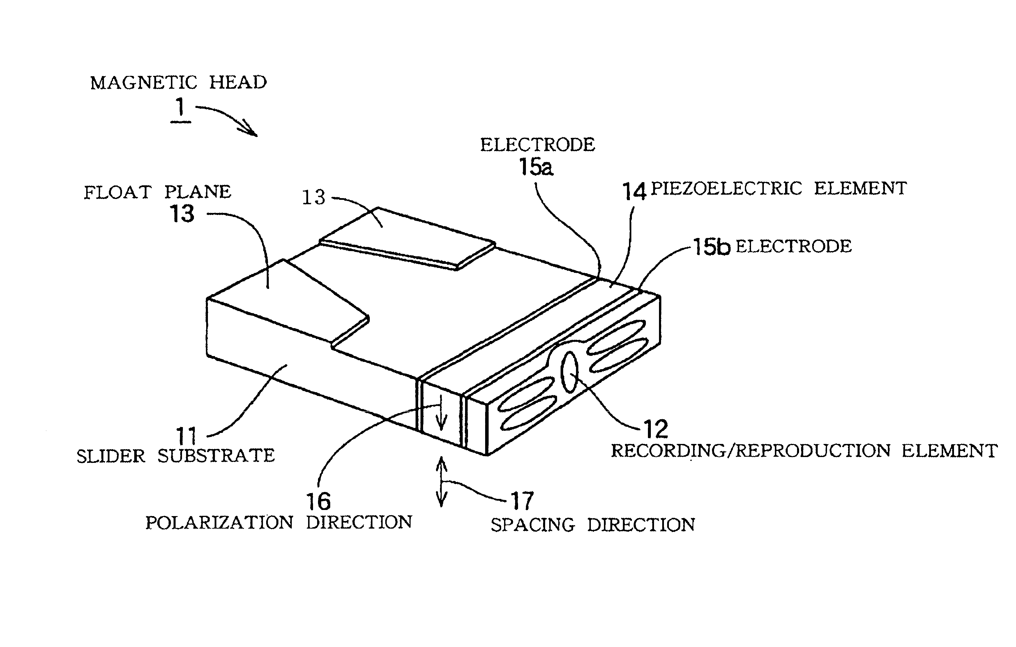
Figure 1 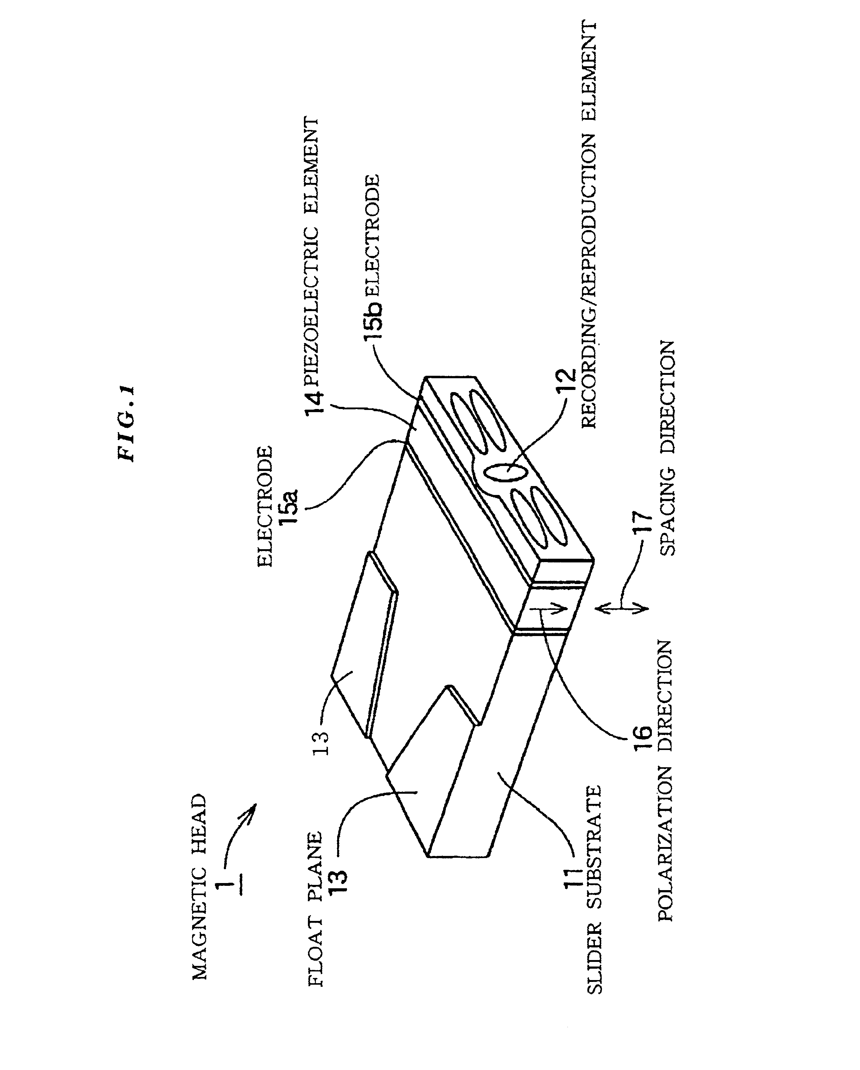
Figure 2 
Figure 3
Abstract
Description
[0001] The present Application is a divisional Application of prior U.S. application Ser. No. 09 / 587,132 filed Jun. 2, 2000 now U.S. Pat. No. 6,487,045.BACKGROUND OF THE INVENTION
[0002] 1. Field of the Invention
[0003] The present invention relates to a magnetic disc apparatus, a magnetic head, and an each production method thereof and in particular, to a magnetic head in which a recording / reproduction element is mounted on a magnetic head slider via a piezoelectric element so that the position of the recording / reproduction element can be adjusted in job mode by displacement of the piezoelectric element, and its production method, a magnetic disc apparatus using the magnetic head, and its production method.
[0004] 2. Description of the Related Art
[0005] In a magnetic disc apparatus, recording density can be increased by increasing the recording density (linear recording density) of the magnetic disc rotation direction and the recording density (track density) of the magnetic disc radial di...
Examples
first embodiment
[0070]FIG. 1 is a perspective view of a magnetic head (magnetic head slider) according to the present invention. FIG. 1 shows a magnetic head floating plane (facing a magnetic disc) upward. The magnetic head (magnetic head slider) shown in FIG. 1 includes a slider substrate 11, a piezoelectric element 14 sandwiched by electrodes 15a and 15b, and a recording / reproduction element 12. A floating plane 13 is formed on the surface of the slider substrate 11.
[0071]The piezoelectric element 14 is attached to the rear end surface (air flow out side) of the slider substrate 11 via one of the electrodes 15a. On the side of the other electrode 15b of the piezoelectric element 14, the recording / reproduction element 12 is arranged.
[0072]The piezoelectric element 14 is displaced when an electric field is applied between the electrodes 15a and 15b. In the case when the polarization direction 16 of the piezoelectric element 14 is vertical to the electric field, the piezoelectric element 14 is displ...
second embodiment
[0082]FIG. 3 is a perspective view of a magnetic head (magnetic head slider) according to the present invention. In the magnetic head (magnetic head slider) 2 shown in FIG. 3, a floating plane 13 is formed on the surface of the slider substrate 11. Moreover, in this magnetic head (magnetic head slider) 2, a piezoelectric element 141 sandwiched by electrodes 15a and 15b is attached to the rear surface of the slider substrate 11 and a recording / reproduction element 12 is arranged via the piezoelectric element 141. The piezoelectric element 141 has a polarization direction 161 vertical to the direction of the electric field.
[0083]In the magnetic head (magnetic head slider) 2 shown in FIG. 3, the polarization direction 161 of the piezoelectric element 141 is the radial direction (track direction) of a magnetic disc. Accordingly, by applying an electric field between the electrodes 15a and 15b, it is possible to displace the recording / reproduction element 12 in the track direction. The e...
third embodiment
[0089]FIG. 4 is a perspective view of a magnetic head (magnetic head slider) according to the present invention. In the magnetic head (magnetic head slider) 3 shown in FIG. 4, a floating plane 13 is formed on the surface of the slider substrate 11. Moreover, in this magnetic head (magnetic head slider) 3, on the rear surface of the slider substrate 11, a piezoelectric element 14 sandwiched between an electrode 15a and a common electrode 15b and a piezoelectric element 141 sandwiched by the common electrode 15b and an electrode 15c are layered, and a recording / reproduction element 12 is arranged on the electrode 15c.
[0090]The piezoelectric element 14 has the polarization direction 16 in the spacing direction 17, and the piezoelectric element 141 has the polarization direction 161 in the track direction 18. Thus, the polarization directions 16 and 161 of the two piezoelectric elements 14 and 141 are in the spacing direction 17 and the track direction 18 which are perpendicular to eac...