
Image reading apparatus and multi-functional apparatus having a plate-like pressing member
a multi-functional, plate-like technology, applied in the direction of electrographic process apparatus, instruments, optics, etc., can solve the problems of limiting the size and position of the wiring circuit board, and affecting the original transport path, so as to facilitate the elimination of failures and reduce the size of the apparatus
Patent Information
- Authority / Receiving Office
- US · United States
- Patent Type
- Patents(United States)
- Current Assignee / Owner
- Publication Date
- 2009-10-06
Smart Images
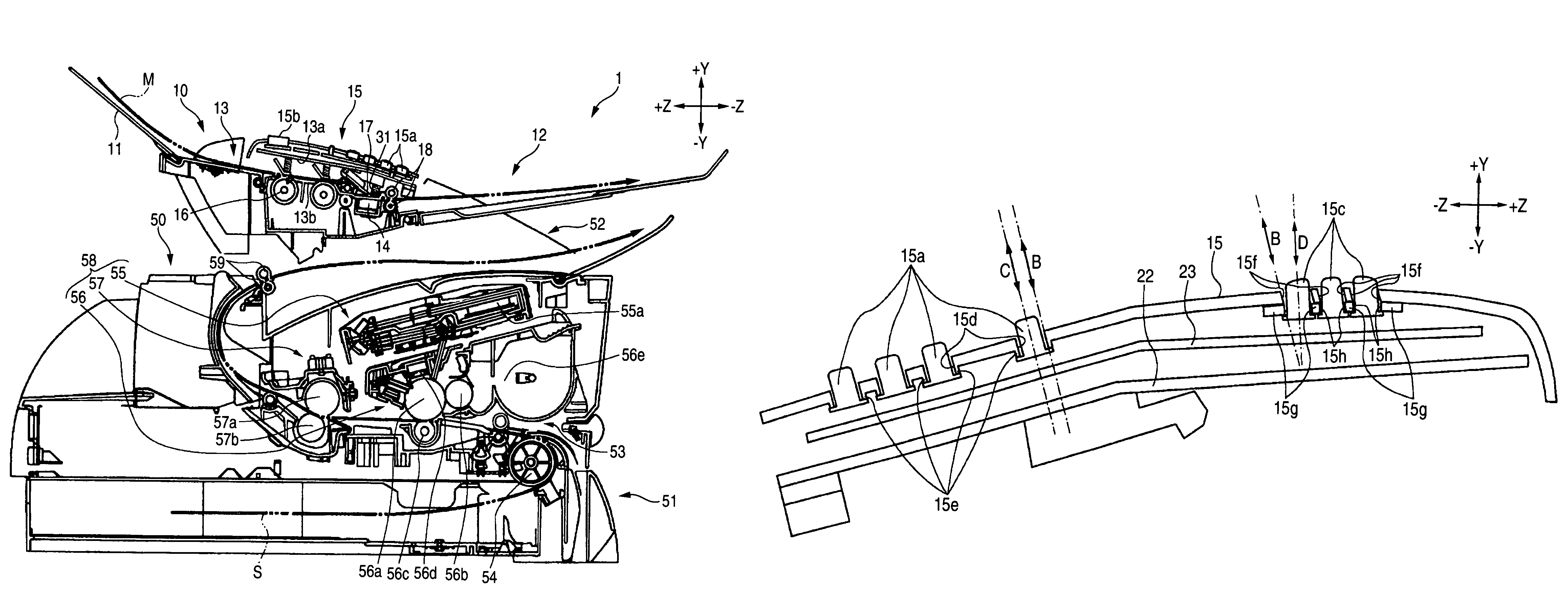
Figure 1 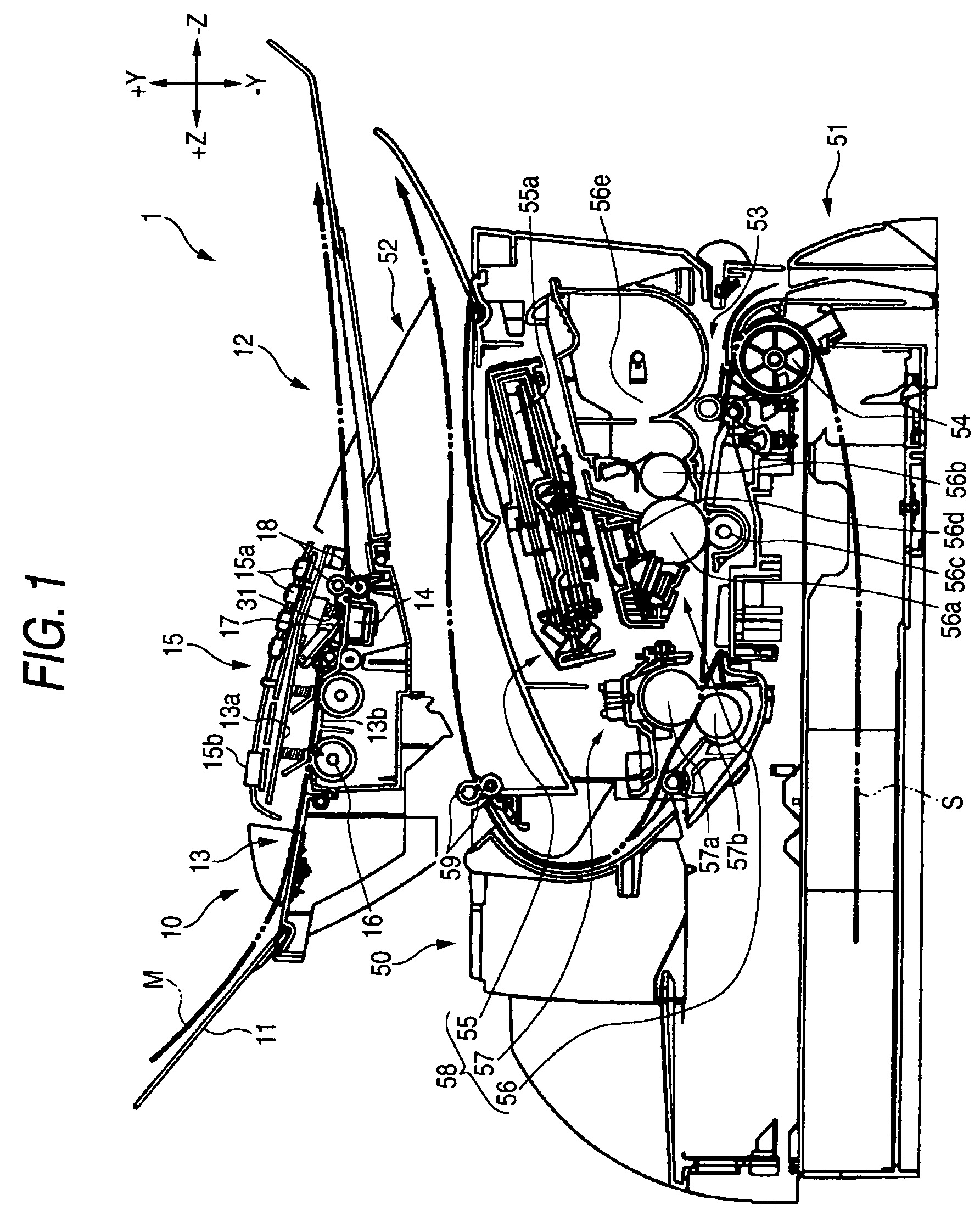
Figure 2 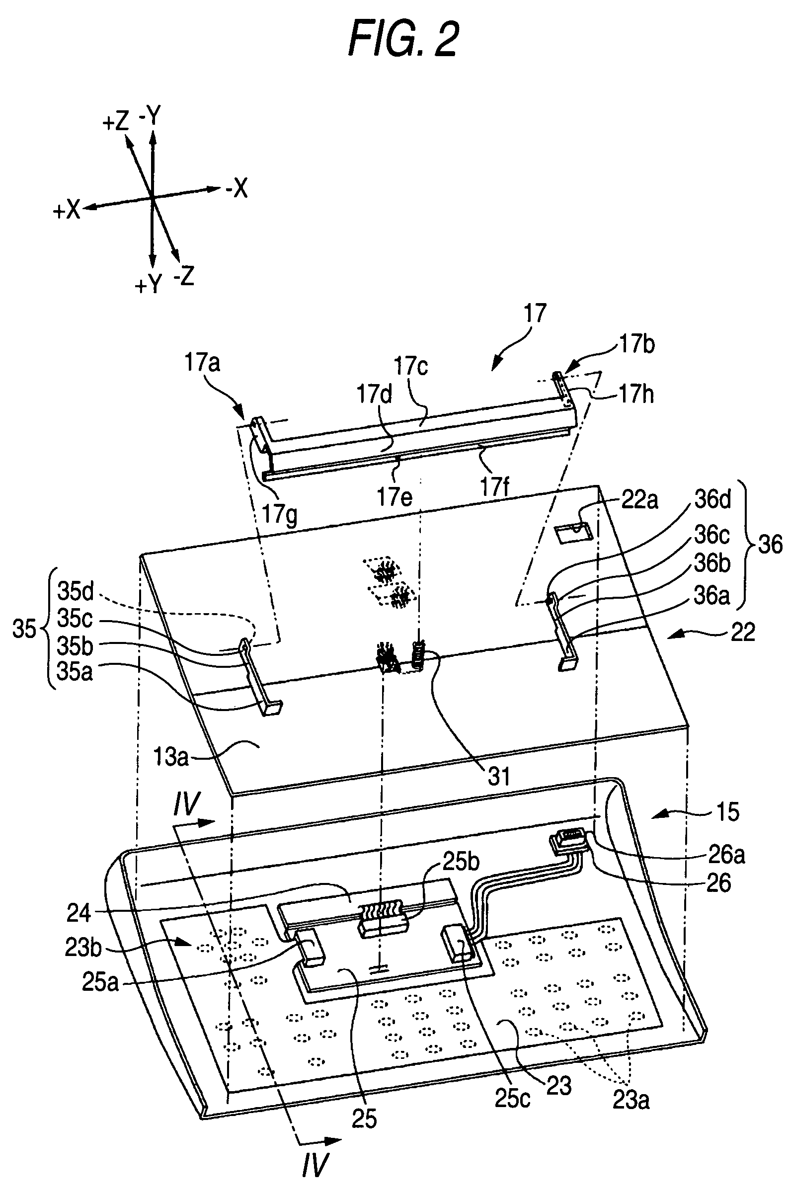
Figure 3
Abstract
Description
BACKGROUND OF THE INVENTION
[0001] 1. Field of the Invention
[0002] The present invention relates to an image reading apparatus in which the size can be reduced, and also to a multi-functional apparatus having such an image reading apparatus.
[0003] 2. Description of the Related Art
[0004] Recently, a multi-functional apparatus which has an image reading apparatus, an image forming apparatus, a facsimile apparatus, and the like, and which can be used in various applications such as a scanner, a fax, a printer, and a copier is in widespread use. In an image reading apparatus mounted in such a multi-functional apparatus, in order to reduce the cost of the multi-functional apparatus, an expensive CCD image sensor is not used in an operation of reading an original serving as a medium to be read, and the reading operation is conducted with using a contact image sensor (hereinafter, abbreviated as “CIS”).
[0005] A CIS has a shallower depth of field than a CCD image sensor. In order to read an image...
Examples
Embodiment Construction
[0028]Hereinafter, an embodiment of an image reading apparatus and a multi-functional apparatus having such an image reading apparatus in which the invention is embodied will be described with reference to the accompanying drawings. Referring to FIG. 1, first, the whole configuration of a multi-functional apparatus 1 will be described. FIG. 1 is a central sectional view of the apparatus 1. Hereinafter, the directions of −Z, +Z, +Y, −Y, +X, and −X are referred to as the front direction, the back direction, the upper direction, the bottom direction, the right side direction, and the left side direction, respectively.
[0029]As shown in FIG. 1, the apparatus 1 has a configuration in which an image reading apparatus 10 for reading an image formed on a medium to be read is placed in an upper portion in the sectional view, and an image forming apparatus 50 for forming an image on a medium to be recorded is placed in a lower portion. The apparatus 1 has: a scanner function due to the image r...