
Drying apparatus
a technology of drying apparatus and airflow, which is applied in the direction of drying machines with progressive movements, cleaning using liquids, furnaces, etc., can solve the problems of insufficient momentum and prior art, and achieve the effect of increasing the momentum of airflow emitted through the opening, increasing the efficiency of the dryer, and achieving a particularly effective level of momentum
Patent Information
- Authority / Receiving Office
- US · United States
- Patent Type
- Patents(United States)
- Current Assignee / Owner
- Publication Date
- 2013-01-08
Smart Images
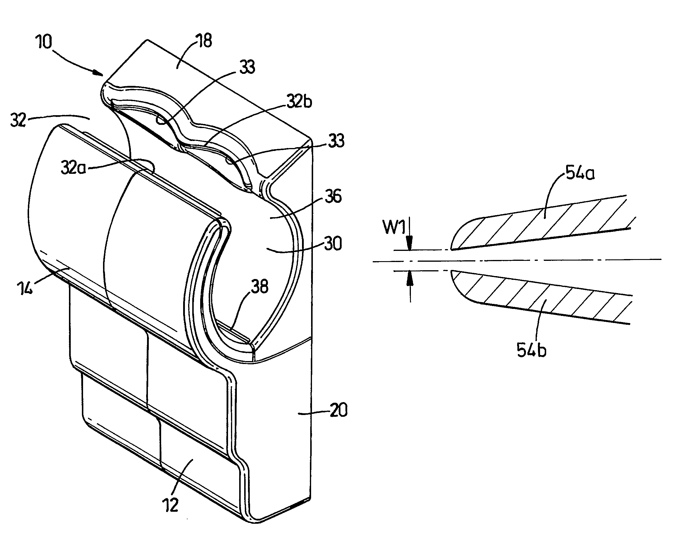
Figure 1 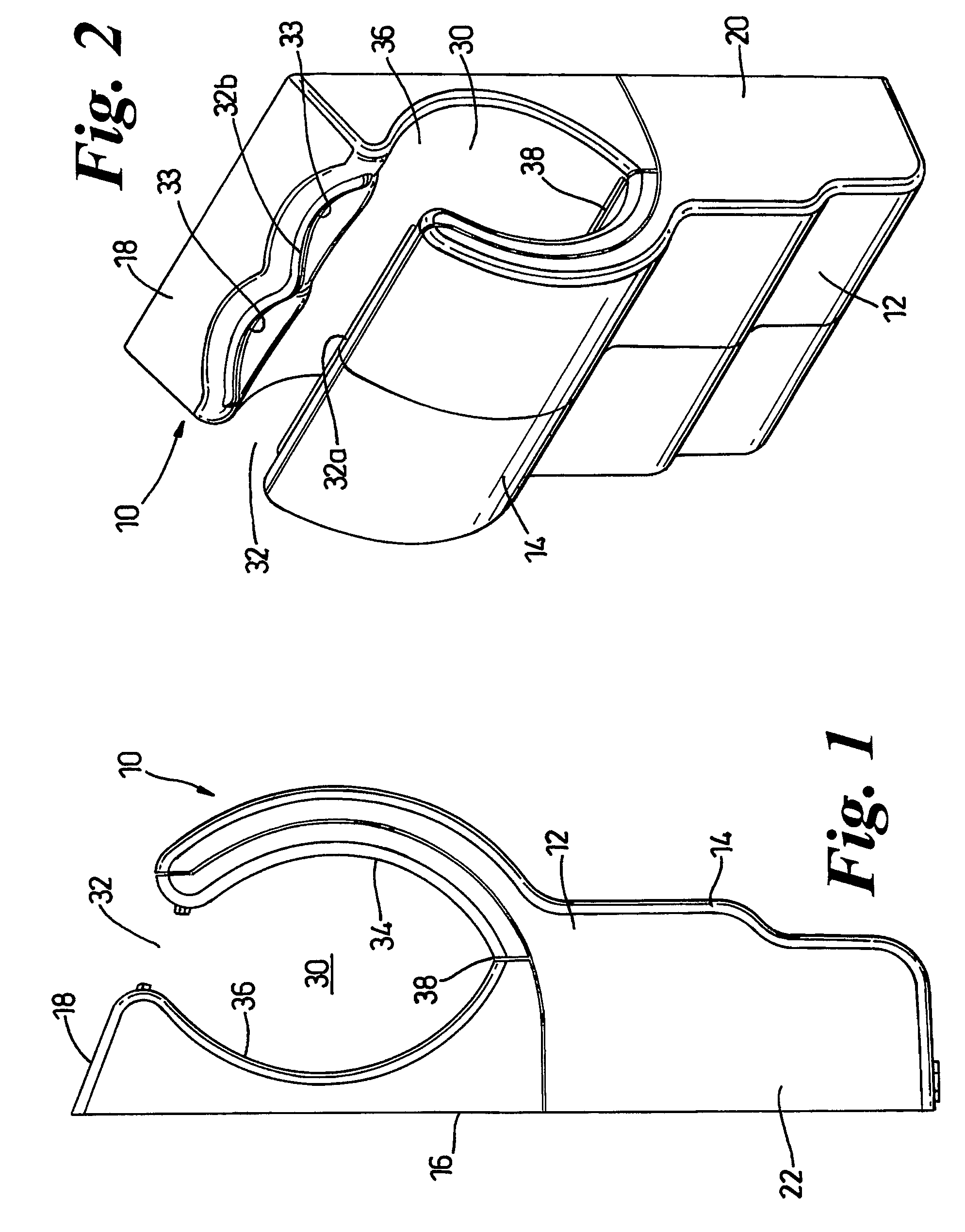
Figure 2 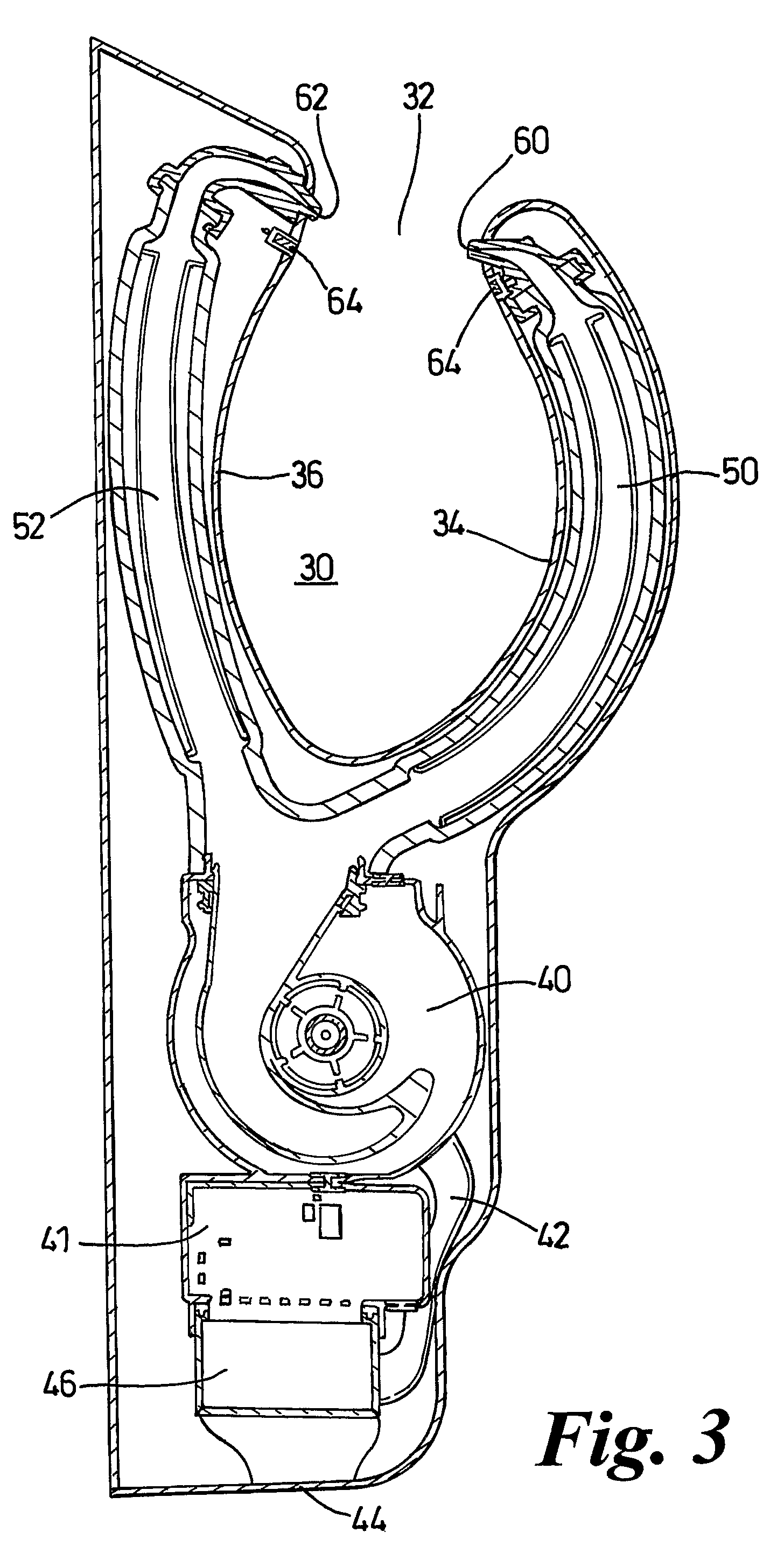
Figure 3
Abstract
Description
REFERENCE TO RELATED APPLICATIONS
[0001] This application is a national stage application under 35 USC 371 of International Application No. PCT / GB2006 / 002093, filed Jun. 7, 2006, which claims the priority of United Kingdom Application Nos. 0515750.8, filed Jul. 30, 2005, and 0600872.6, filed Jan. 17, 2006, the contents of which prior applications are incorporated herein by reference.FIELD OF THE INVENTION
[0002] The invention relates to drying apparatus which makes use of a narrow jet of high velocity, high pressure air to dry an object, including part of the human body. Particularly, but not exclusively, the invention relates to a hand dryer in which the air jet is emitted through a slot-like opening in the casing of the hand dryer.BACKGROUND OF THE INVENTION
[0003] The use of air jets to dry hands is well known. Examples of hand dryers which emit at least one air jet through a slot-like opening are shown in GB 2249026A, JP 2002-034835A and JP 2002-306370A. However, in practice it is ver...
Examples
Embodiment Construction
[0018]Referring firstly to FIGS. 1 and 2, the hand dryer 10 shown in FIGS. 1 to 6 comprises an outer casing 12 having a front wall 14, a rear wall 16, an upper face 18 and side walls 20, 22. The rear wall 16 can incorporate fixing devices (not shown) for securing the hand dryer 10 to a wall or other structure prior to use. An electrical connection (not shown) is also provided on the rear wall or elsewhere on the casing 12. A cavity 30 is formed in the upper part of the casing 12 as can be seen from FIGS. 1 and 2. The cavity 30 is open at its upper end and delimited thereat by the top of the front wall 14 and the front of the upper face 18. The space between the top of the front wall 14 and the front of the upper face 18 forms a cavity entrance 32 which is sufficiently wide to allow a user's hands to be introduced to the cavity 30 through the cavity entrance 32. The cavity 30 is also open to the sides of the hand dryer 10 by appropriate shaping of the side walls 20, 22.
[0019]The cavi...