
Adjustable spinal rehabilitation device
a spinal rehabilitation and adjustable technology, applied in the field of adjustable spinal rehabilitation devices, can solve the problems of compromising the quality of spine-stretching rehabilitation therapy and the efficacy of rehabilitation beds, inconvenient use of rehabilitation beds, and the inability to ergonomically adjust the inclination of rehabilitation beds, so as to improve the efficacy of rehabilitation therapy.
Patent Information
- Authority / Receiving Office
- US · United States
- Patent Type
- Patents(United States)
- Current Assignee / Owner
- Publication Date
- 2013-04-30
- Estimated Expiration
- Not applicable · inactive patent
Smart Images
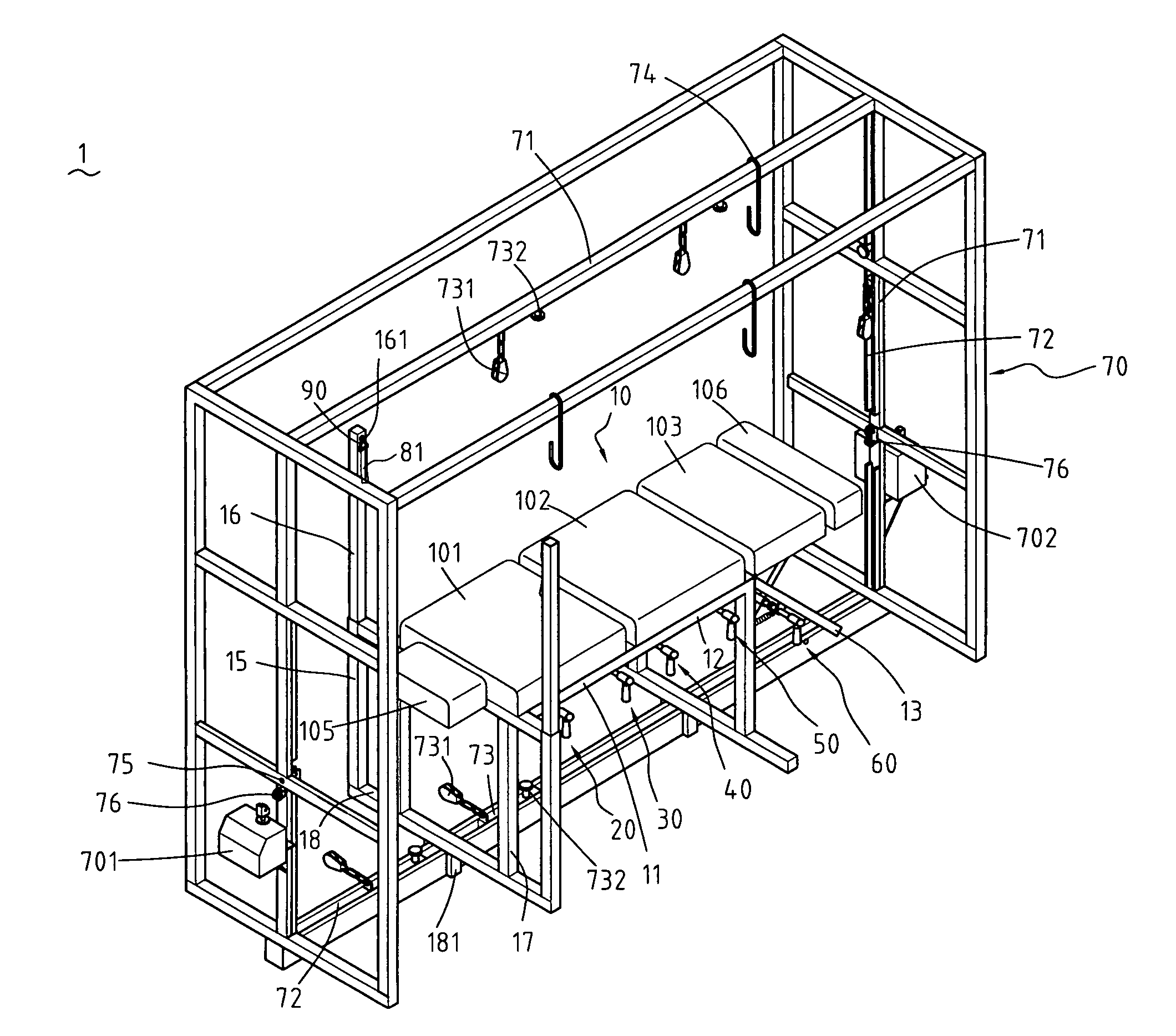
Figure 1 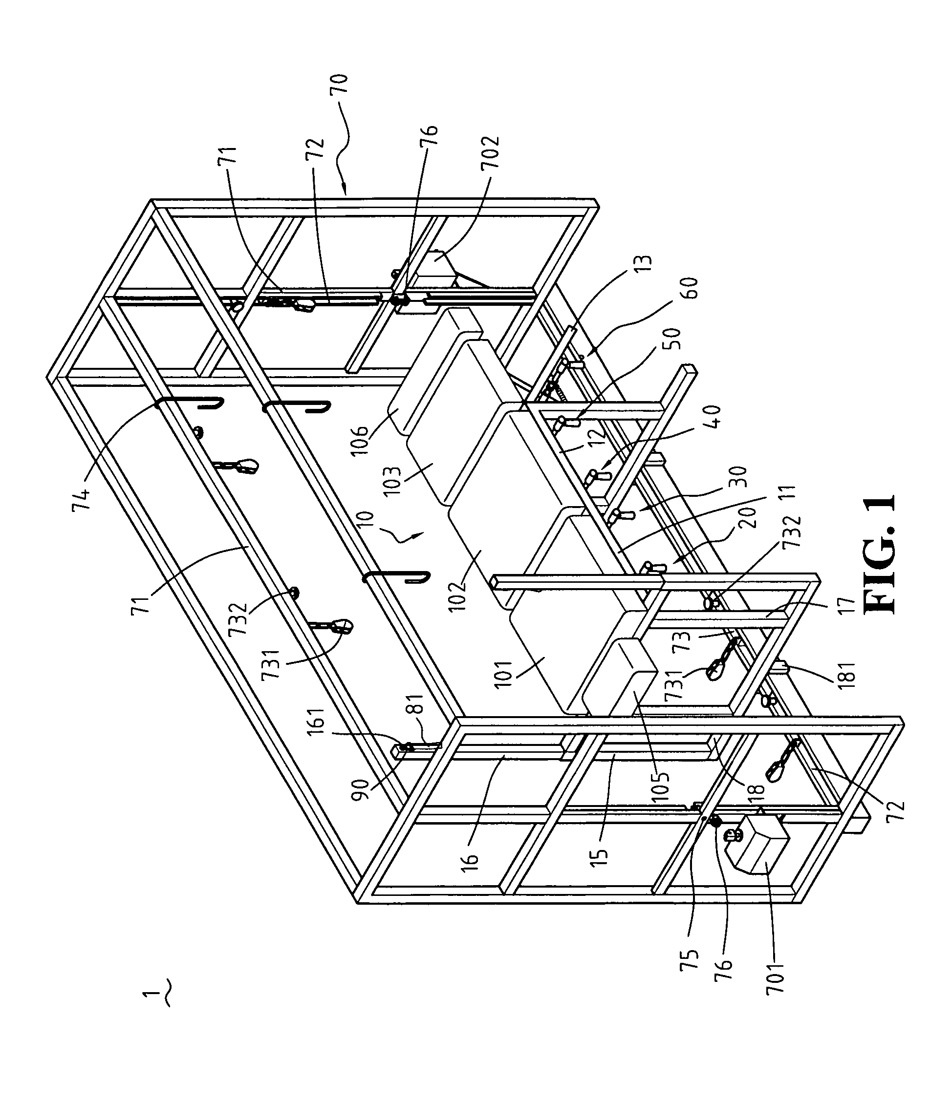
Figure 2 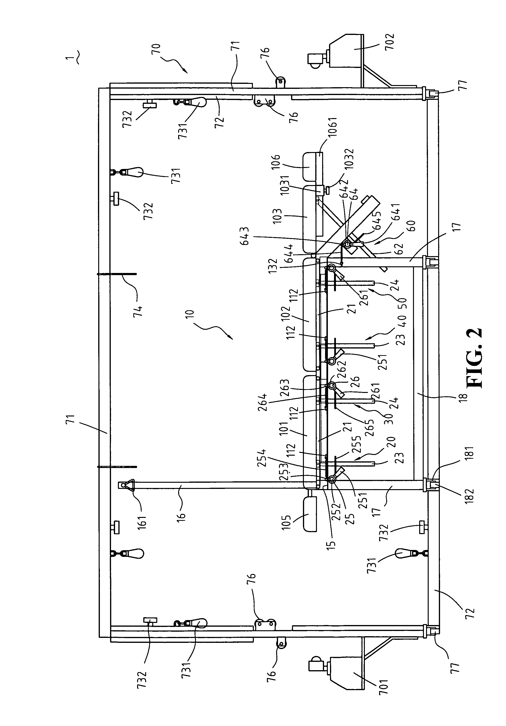
Figure 3
Abstract
Description
FIELD OF THE INVENTION
[0001] The present invention relates to adjustable spinal rehabilitation devices, and more particularly, to a three-dimensional spinal rehabilitation device equipped with elevation adjustment mechanisms for adjusting inclinations of pads on a bed frame and equipped with an inverted U-shaped frame having pulley trains and two tractors, so as to give a pull at a rehabilitation patient's spine from the front or sideward, with the rehabilitation patient lying on the pads of adjustable inclinations.BACKGROUND OF THE INVENTION
[0002] U.S. Pat. No. 7,127,757, entitled Adjustable Traction Table, discloses a rehabilitation bed capable of being raised at an angle to the horizontal so as for a rehabilitation patient lying on the rehabilitation bed to receive spinal rehabilitation therapy. However, after putting the rehabilitation patient in place on the rehabilitation bed, moving the rails thereunder, and adjusting four jacks to change inclination of the two-segment rehabili...
Examples
Embodiment Construction
[0022]Referring to FIG. 1 through FIG. 7, and FIG. 9, the present invention provides an adjustable spinal rehabilitation device 1, comprising: a bed frame 10, a first pad 101, a second pad 102, a third pad 103, a fourth pad 104, a head pad 105, a foot pad 106, a first elevation adjustment mechanism 20, a second elevation adjustment mechanism 30, a third elevation adjustment mechanism 40, a fourth elevation adjustment mechanism 50, a fifth elevation adjustment mechanism 60, an inverted U-shaped frame 70, a first tractor 701, and a second tractor 702. The above-mentioned are described in detail hereunder.
[0023]Referring to FIG. 1 and FIG. 2, the bed frame 10 comprises a chest-section frame 11, a belly-section frame 12, and a leg-section frame 13. The leg-section frame 13 slants downward. The bed frame 10 is flanked by rods 14 horizontally positioned (see FIG. 9). Hollow posts 15 are provided on two sides of the chest-section frame 11. Rods 16 are inserted into the hollow posts 15, res...