How to Troubleshoot Common Multiplexer Signal Issues?
JUL 13, 20259 MIN READ
Generate Your Research Report Instantly with AI Agent
Patsnap Eureka helps you evaluate technical feasibility & market potential.
Multiplexer Fundamentals
Multiplexers are fundamental components in digital systems, playing a crucial role in signal routing and data selection. These devices allow multiple input signals to be selectively transmitted through a single output channel, effectively reducing the number of wires and components required in complex circuits. The basic principle of multiplexing involves using control signals to select one of several input lines and connect it to the output.
In digital systems, multiplexers are commonly used for various applications, including data selection, address decoding, and parallel-to-serial conversion. They come in different sizes, with the most common configurations being 2-to-1, 4-to-1, 8-to-1, and 16-to-1 multiplexers. The size of a multiplexer is determined by the number of input lines it can handle and the number of select lines required to choose the desired input.
The operation of a multiplexer is based on binary logic. For example, a 4-to-1 multiplexer requires two select lines to choose one of the four input lines. The select lines are typically controlled by a binary code, where 00 might select the first input, 01 the second, 10 the third, and 11 the fourth. This binary selection mechanism allows for efficient and precise control of signal routing within a circuit.
Multiplexers can be implemented using various technologies, including discrete logic gates, integrated circuits, or programmable logic devices. In modern integrated circuits, multiplexers are often built into more complex devices such as microprocessors, field-programmable gate arrays (FPGAs), and application-specific integrated circuits (ASICs).
When troubleshooting multiplexer signal issues, it is essential to understand the device's internal structure and operation. A typical multiplexer consists of input buffers, select line decoders, and output drivers. Each of these components can be a potential source of signal problems. Input buffers ensure that the incoming signals are properly conditioned and isolated from the internal circuitry. The select line decoder interprets the control signals and activates the appropriate signal path. Output drivers provide the necessary current and voltage levels to transmit the selected signal to the next stage of the circuit.
Common issues that may arise in multiplexer circuits include signal degradation, crosstalk between channels, timing misalignments, and incorrect selection due to faulty control logic. Signal degradation can occur due to impedance mismatches, excessive capacitive loading, or inadequate power supply decoupling. Crosstalk, where signals from one channel interfere with another, may result from poor PCB layout or insufficient shielding between signal paths.
Understanding these fundamental aspects of multiplexers is crucial for effective troubleshooting of signal issues. By recognizing the internal structure, operation principles, and potential failure modes, engineers can develop systematic approaches to identify and resolve problems in multiplexer-based circuits.
Signal Integrity Demands
Signal integrity has become a critical concern in modern electronic systems, particularly in high-speed digital designs and complex multiplexer configurations. As data rates continue to increase and signal paths become more intricate, maintaining signal quality throughout the transmission process is paramount. The demand for robust signal integrity in multiplexer systems stems from the need to preserve data accuracy, reduce errors, and ensure reliable communication between various components.
In multiplexer applications, signal integrity challenges are exacerbated by the switching nature of these devices. As multiplexers route signals from multiple inputs to a single output, they introduce potential sources of signal degradation, including crosstalk, reflections, and timing issues. These problems can lead to data corruption, increased bit error rates, and overall system performance degradation.
The increasing complexity of electronic systems, coupled with the push for higher bandwidth and faster data transmission, has further intensified the focus on signal integrity. Modern applications, such as 5G networks, high-speed computing, and advanced automotive systems, demand multiplexers capable of handling gigabit-per-second data rates while maintaining signal fidelity. This necessitates careful consideration of factors such as impedance matching, signal routing, and power distribution network design.
Moreover, the miniaturization trend in electronics has led to denser circuit boards and more compact multiplexer packages. This reduction in physical space between signal paths increases the likelihood of electromagnetic interference and crosstalk, further emphasizing the need for robust signal integrity solutions. Engineers must now consider not only the electrical characteristics of the multiplexer itself but also its interaction with surrounding components and the overall system environment.
The demand for improved signal integrity in multiplexer systems has driven innovations in both hardware and software domains. On the hardware side, advanced materials and manufacturing techniques are being employed to create multiplexers with better isolation between channels and reduced parasitic effects. Simultaneously, sophisticated signal processing algorithms and error correction techniques are being developed to compensate for signal degradation and improve overall system performance.
As the complexity of electronic systems continues to grow, so does the importance of comprehensive signal integrity analysis and testing. Design engineers are increasingly relying on advanced simulation tools and measurement equipment to predict and mitigate signal integrity issues in multiplexer designs. This proactive approach helps identify potential problems early in the development cycle, reducing time-to-market and improving product reliability.
Common Multiplexer Faults
Multiplexers are essential components in many electronic systems, but they can be prone to various faults that affect signal integrity and overall system performance. Common multiplexer faults can be categorized into several types, each with distinct characteristics and potential causes.
Signal crosstalk is one of the most prevalent issues in multiplexer circuits. This occurs when signals from adjacent channels interfere with each other, leading to distortion and data corruption. Crosstalk can be caused by inadequate shielding, poor PCB layout, or insufficient isolation between channels. In high-frequency applications, crosstalk becomes more pronounced and can significantly degrade signal quality.
Another common fault is signal attenuation, where the output signal is weaker than the input signal. This can be due to various factors, including excessive cable length, impedance mismatches, or faulty components within the multiplexer. Signal attenuation can result in reduced signal-to-noise ratio and increased bit error rates in digital systems.
Timing issues are also frequently encountered in multiplexer circuits. These can manifest as skew between channels, where signals arrive at different times, or as jitter, which is the variation in signal timing. Timing faults can be caused by clock distribution problems, uneven trace lengths, or variations in component characteristics. In high-speed applications, even small timing discrepancies can lead to synchronization errors and data loss.
Multiplexer faults can also arise from power supply issues. Voltage fluctuations or noise on the power rails can introduce unwanted artifacts into the signal path. This can result in intermittent errors, signal distortion, or complete failure of the multiplexer. Proper power supply decoupling and filtering are crucial to mitigate these issues.
Component failures within the multiplexer itself can lead to various faults. These may include stuck channels, where a particular input is always selected regardless of the control signals, or non-responsive channels that fail to pass any signal. Such failures can be caused by manufacturing defects, electrical overstress, or environmental factors like temperature extremes or moisture ingress.
Electrostatic discharge (ESD) events can also cause multiplexer faults. ESD can damage sensitive input stages, leading to degraded performance or complete failure of affected channels. Proper ESD protection measures, including on-chip protection circuits and careful handling procedures, are essential to prevent such damage.
In digital multiplexers, logic errors in the control circuitry can result in incorrect channel selection or switching. This may be due to software bugs, firmware issues, or hardware faults in the control logic. Such errors can lead to unpredictable behavior and data routing problems in complex systems.
Troubleshooting Techniques
01 Multiplexer signal processing and transmission
Multiplexers are used to process and transmit multiple signals over a single channel. This involves combining several input signals into one output signal, allowing for efficient use of communication bandwidth. The technology includes methods for signal selection, switching, and synchronization to ensure accurate data transmission.- Multiplexer signal processing and transmission: Multiplexers are used to combine multiple input signals into a single output signal for efficient transmission. This involves techniques for signal selection, switching, and encoding to ensure accurate data transfer across communication channels.
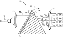
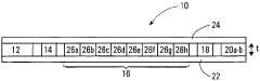
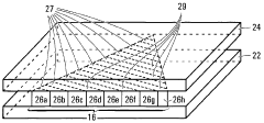
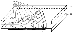
- Optical multiplexing systems: Optical multiplexers are employed in fiber optic communications to combine multiple wavelengths of light for transmission over a single fiber. These systems often involve wavelength division multiplexing (WDM) techniques and optical signal processing.
- Digital multiplexer design and implementation: Digital multiplexers are crucial components in electronic circuits for selecting and routing digital signals. This includes the design of multiplexer logic, control circuitry, and integration with other digital components for various applications.
- Multiplexer error detection and correction: Techniques for detecting and correcting errors in multiplexed signals are essential for maintaining data integrity. This involves implementing error checking algorithms, redundancy schemes, and recovery mechanisms in multiplexer systems.
- Time-division multiplexing techniques: Time-division multiplexing (TDM) is a method used to transmit multiple signals over a single channel by allocating time slots to each signal. This involves synchronization, timing control, and efficient allocation of bandwidth in communication systems.
02 Optical multiplexing techniques
Optical multiplexing involves combining multiple optical signals into a single fiber optic transmission. This technology is crucial for increasing data capacity in fiber optic networks. It includes wavelength division multiplexing (WDM) and time division multiplexing (TDM) techniques for efficient signal transmission in optical communication systems.Expand Specific Solutions03 Digital signal multiplexing and demultiplexing
Digital multiplexing techniques are used to combine multiple digital signals into a single bitstream for transmission. This involves encoding, interleaving, and synchronization of digital data. Demultiplexing is the reverse process, separating the combined signal back into its original components at the receiver end.Expand Specific Solutions04 Error detection and correction in multiplexed signals
Multiplexed signals are susceptible to errors during transmission. Various error detection and correction techniques are employed to ensure data integrity. These include forward error correction, cyclic redundancy checks, and adaptive error correction algorithms tailored for multiplexed signal environments.Expand Specific Solutions05 Multiplexer design for low power and high-speed applications
Advanced multiplexer designs focus on reducing power consumption while maintaining high-speed operation. This involves innovative circuit topologies, use of low-power semiconductor technologies, and optimization of signal routing. These designs are crucial for applications in mobile devices, data centers, and high-performance computing systems.Expand Specific Solutions
Key Multiplexer Manufacturers
The multiplexer signal troubleshooting market is in a mature stage, with a stable global market size estimated in the billions of dollars. The technology is well-established, with key players like Samsung Display, NEC, and Qualcomm leading innovation. These companies have developed advanced solutions for common issues such as signal crosstalk, timing errors, and power management. Emerging players like Malikie Innovations and Alpine Optoelectronics are introducing novel approaches, focusing on high-speed applications and improved signal integrity. The competitive landscape is characterized by a mix of established electronics giants and specialized niche providers, with ongoing research and development efforts aimed at enhancing multiplexer performance and reliability across various industries.
QUALCOMM, Inc.
Technical Solution: QUALCOMM has developed advanced multiplexer troubleshooting techniques for their mobile communication systems. They utilize a combination of hardware and software solutions to address common signal issues. Their approach includes real-time signal monitoring and adaptive algorithms that can detect and correct signal degradation, crosstalk, and interference[1]. QUALCOMM's system employs advanced digital signal processing (DSP) techniques to analyze and optimize multiplexed signals, ensuring high-quality data transmission even in challenging environments[3]. They have also implemented machine learning algorithms to predict and preemptively address potential signal issues, significantly reducing downtime and improving overall system reliability[5].
Strengths: Cutting-edge DSP and machine learning integration, real-time adaptive solutions. Weaknesses: May require specialized hardware, potentially higher implementation costs.
Samsung Electronics Co., Ltd.
Technical Solution: Samsung Electronics has developed a comprehensive approach to troubleshooting multiplexer signal issues in their diverse product range, from consumer electronics to semiconductor devices. Their strategy involves a combination of hardware design optimization and advanced software algorithms. Samsung utilizes adaptive equalization techniques and decision feedback equalizers (DFE) to compensate for channel impairments and improve signal quality in high-speed digital interfaces[8]. They have also implemented advanced clock and data recovery (CDR) circuits to maintain signal synchronization and reduce jitter in multiplexed systems[10]. Samsung's troubleshooting toolkit includes automated test equipment (ATE) with high-speed signal generators and analyzers, enabling precise characterization of multiplexer performance and rapid identification of signal integrity issues[12].
Strengths: Broad expertise across consumer and industrial applications, advanced signal processing techniques. Weaknesses: Solutions may be optimized for Samsung's specific hardware platforms.
Advanced Diagnostic Tools
Wavelength multiplexer/demultiplexer comprising an optically dispersive stratified body
PatentWO2005052662A1
Innovation
- A wavelength multiplexer/demultiplexer comprising a stratified body with regions of optically permissive materials having differing indexes of refraction, positioned in a side-by-side relationship with non-parallel light-receiving and light-exiting surfaces, which enhances optical dispersion for effective separation and recombination of wavelength components.
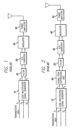
Method for peak power reduction in spread spectrum communications systems
PatentInactiveUS7003017B2
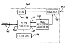
Innovation
- A peak reduction unit is introduced before the filter in the system, which predicts the filter's effect on input symbols and reduces only those that would exceed a predetermined peak limit, using filter impulse response coefficients to adjust symbols on a symbol-by-symbol basis, thereby minimizing distortion and maintaining spectral characteristics.
EMI/EMC Considerations
Electromagnetic Interference (EMI) and Electromagnetic Compatibility (EMC) are critical considerations when troubleshooting common multiplexer signal issues. Multiplexers, being integral components in many electronic systems, can both generate and be susceptible to electromagnetic interference, which can significantly impact signal integrity and overall system performance.
In the context of multiplexer signal troubleshooting, EMI can manifest as unwanted noise or distortion in the multiplexed signals. This interference can originate from various sources, including nearby electronic devices, power supplies, or even other components within the same system. The high-speed switching nature of multiplexers can also contribute to EMI generation, potentially affecting other sensitive circuits in the vicinity.
To address EMI concerns, proper shielding techniques are essential. This may involve using metal enclosures, conductive gaskets, or specialized EMI-suppressing materials to contain electromagnetic emissions and protect the multiplexer circuitry from external interference. Additionally, implementing effective grounding strategies can help minimize ground loops and reduce the impact of common-mode noise on multiplexed signals.
Signal routing and PCB layout play crucial roles in EMC considerations for multiplexers. Careful attention must be paid to the placement of signal traces, ensuring adequate separation between high-speed digital lines and sensitive analog signals. The use of differential signaling techniques can also enhance immunity to common-mode noise and improve overall signal integrity in multiplexer applications.
Power supply decoupling is another critical aspect of EMC design for multiplexers. Proper selection and placement of bypass capacitors can help suppress high-frequency noise on power rails, reducing the likelihood of EMI-induced signal degradation. In some cases, the use of ferrite beads or other filtering components may be necessary to further attenuate power supply noise.
When troubleshooting multiplexer signal issues related to EMI/EMC, it is important to consider the entire signal chain, including input sources, interconnects, and load terminations. Each of these elements can contribute to or be affected by electromagnetic interference, necessitating a holistic approach to problem-solving.
Compliance with relevant EMC standards and regulations is also a key consideration in multiplexer design and troubleshooting. Depending on the application and target market, specific EMI emission and susceptibility limits may need to be met. This often requires comprehensive EMC testing and validation procedures to ensure that the multiplexer system performs reliably in its intended electromagnetic environment.
Reliability Testing Methods
Reliability testing methods play a crucial role in troubleshooting common multiplexer signal issues. These methods are designed to assess the performance and durability of multiplexer systems under various conditions, ensuring their ability to maintain signal integrity over time.
One of the primary reliability testing methods for multiplexers is environmental stress testing. This involves subjecting the device to extreme temperature variations, humidity levels, and vibration to simulate real-world operating conditions. By exposing the multiplexer to these stressors, engineers can identify potential weak points in the system and develop solutions to enhance its resilience.
Signal integrity testing is another essential method for evaluating multiplexer reliability. This process involves measuring key parameters such as signal-to-noise ratio, crosstalk, and jitter across different channels. By analyzing these metrics, technicians can pinpoint sources of signal degradation and implement corrective measures to optimize performance.
Accelerated life testing is a valuable technique for predicting the long-term reliability of multiplexer systems. This method involves operating the device under elevated stress conditions to simulate extended use in a compressed timeframe. By analyzing the results of accelerated life tests, engineers can estimate the mean time between failures (MTBF) and identify potential failure modes before they occur in the field.
Burn-in testing is another critical reliability testing method for multiplexers. This process involves operating the device at elevated temperatures for an extended period to identify and eliminate early-life failures. By subjecting the multiplexer to this stress, manufacturers can ensure that only robust units are shipped to customers, reducing the likelihood of field failures.
Electromagnetic compatibility (EMC) testing is essential for assessing a multiplexer's ability to function correctly in the presence of electromagnetic interference. This method involves subjecting the device to various electromagnetic disturbances and measuring its performance under these conditions. EMC testing helps ensure that the multiplexer can maintain signal integrity in real-world environments where electromagnetic interference is common.
Functional testing under various load conditions is another crucial aspect of multiplexer reliability assessment. This method involves evaluating the device's performance across different channel configurations and signal loads to ensure consistent operation across all possible use cases. By conducting thorough functional testing, engineers can identify and address any limitations or inconsistencies in the multiplexer's performance.
Unlock deeper insights with Patsnap Eureka Quick Research — get a full tech report to explore trends and direct your research. Try now!
Generate Your Research Report Instantly with AI Agent
Supercharge your innovation with Patsnap Eureka AI Agent Platform!