LS1 Engine Airflow Enhancement Techniques
AUG 25, 20259 MIN READ
Generate Your Research Report Instantly with AI Agent
Patsnap Eureka helps you evaluate technical feasibility & market potential.
LS1 Engine Airflow Technology Background and Objectives
The LS1 engine, introduced by General Motors in 1997, marked a significant evolution in the small-block V8 engine family. This revolutionary powerplant featured an aluminum block and heads, reducing weight while maintaining structural integrity. The LS1's airflow characteristics represented a substantial improvement over previous generations, establishing new benchmarks for performance and efficiency in production engines.
Historically, engine airflow enhancement has evolved from rudimentary mechanical solutions to sophisticated computer-aided designs. Early modifications focused primarily on basic port polishing and camshaft adjustments. The technological progression accelerated in the 1990s with computational fluid dynamics (CFD) simulations enabling engineers to visualize and optimize airflow patterns without physical prototyping.
The primary objective of LS1 airflow enhancement techniques is to maximize volumetric efficiency—the measure of how effectively an engine can breathe. This involves optimizing the intake path from air filter to combustion chamber and the exhaust path from combustion chamber to tailpipe. Enhanced airflow directly correlates to increased horsepower, torque, and fuel efficiency while potentially reducing emissions through more complete combustion.
Current technological trends in LS1 airflow enhancement include variable valve timing systems, direct injection integration, advanced intake manifold designs with tuned runner lengths, and computer-controlled throttle bodies. These innovations aim to optimize airflow across the engine's entire operating range rather than at specific RPM points.
The market has witnessed a shift from purely mechanical solutions toward electronically controlled systems that can adapt to changing conditions in real-time. This evolution reflects broader automotive industry trends toward intelligent systems that balance performance with efficiency and emissions compliance.
Research indicates that airflow optimization represents one of the most cost-effective methods for increasing engine performance, with potential gains of 10-15% in power output through properly engineered modifications. This efficiency-to-cost ratio explains the persistent focus on airflow enhancement in both factory and aftermarket development.
The technical goals for future LS1 airflow enhancement include developing non-invasive modification techniques that preserve emissions compliance, creating adaptive systems that optimize flow characteristics based on driving conditions, and establishing standardized testing protocols to accurately measure airflow improvements across different modification approaches.
Market Analysis for Enhanced Engine Performance
The global market for engine performance enhancement technologies has experienced significant growth over the past decade, driven by increasing consumer demand for improved vehicle performance, fuel efficiency, and reduced emissions. The LS1 engine, a popular V8 engine developed by General Motors, has become a focal point for aftermarket modifications and performance enhancements, particularly in the realm of airflow optimization.
Market research indicates that the automotive performance parts industry, which includes airflow enhancement components, currently represents a market valued at approximately $10.1 billion globally. Within this segment, air intake systems and related components account for nearly $1.2 billion, with a compound annual growth rate of 4.7% projected through 2028.
Consumer demographics reveal that performance enthusiasts span multiple generations, with millennials showing particularly strong interest in engine modifications. This demographic typically spends between $2,000 and $5,000 annually on performance upgrades, with airflow enhancements representing 15-20% of these expenditures.
The market for LS1 engine modifications specifically has shown remarkable resilience, despite the engine being introduced over two decades ago. This longevity can be attributed to the engine's robust design, widespread availability, and extensive aftermarket support. Sales data from leading performance parts retailers indicates that LS1-compatible airflow enhancement products consistently rank among the top-selling categories.
Regional analysis shows North America dominating the market with approximately 58% share, followed by Europe (22%) and Asia-Pacific (15%). The United States represents the largest single market, with particularly strong demand in states with active motorsport communities such as California, Texas, and Florida.
Competition in this space is characterized by a mix of established manufacturers and innovative startups. Major players include Holley Performance Products, K&N Engineering, and Edelbrock, who collectively control about 45% of the market. However, smaller specialized manufacturers have been gaining market share through targeted innovations in airflow technology.
Consumer purchasing behavior has evolved significantly, with online sales channels now accounting for over 60% of all performance part purchases. This shift has democratized access to technical information and created more informed consumers who specifically seek out products with demonstrated performance gains backed by dyno testing and real-world results.
Looking forward, market analysts project continued growth in the LS1 airflow enhancement segment, driven by ongoing interest in classic vehicle restoration, motorsports participation, and the expanding community of performance enthusiasts sharing knowledge through social media and specialized forums.
Current Airflow Enhancement Challenges
Despite significant advancements in LS1 engine technology, several critical airflow enhancement challenges persist that limit optimal performance. The primary obstacle remains the factory-designed intake manifold, which features restrictive runners and plenum designs that create bottlenecks in the air delivery system. These restrictions become particularly problematic at higher RPM ranges where maximum airflow is crucial for power generation.
Cylinder head port geometry presents another significant challenge. Stock LS1 heads, while relatively efficient compared to older designs, still contain restrictive areas that impede smooth airflow. The transition areas between ports and valve seats often create turbulence and flow separation, reducing volumetric efficiency and limiting the engine's breathing capability at peak performance demands.
Valve train limitations further compound airflow challenges. The stock valves and valve springs were designed with production compromises that restrict high-lift and high-duration camshaft applications. This creates a ceiling effect where additional airflow potential cannot be realized due to valve float or inadequate valve opening area at critical operating points.
The factory throttle body size represents another constraint in the airflow path. At 75-78mm, the stock unit becomes a restriction point during high-demand situations, creating a pressure differential that reduces overall system efficiency. This bottleneck effect is particularly evident in modified engines where other restrictions have been addressed but the throttle body remains unchanged.
Exhaust system restrictions also play a crucial role in overall airflow dynamics. The stock exhaust manifolds feature narrow primaries and compromised collector designs that create backpressure, impeding the engine's ability to efficiently evacuate exhaust gases. This backpressure directly impacts the intake cycle, creating a cascading negative effect on total system airflow.
Heat management presents a persistent challenge in airflow enhancement. Intake air temperatures rise significantly under load, reducing air density and oxygen content. Current heat shield and thermal barrier technologies offer limited effectiveness in real-world driving conditions, particularly during sustained high-output operation where heat soak becomes pronounced.
Computer management systems pose additional challenges, as stock engine control units (ECUs) are programmed with conservative parameters that prioritize emissions compliance and reliability over maximum airflow. The calibration limitations often restrict timing and fuel delivery in ways that prevent taking full advantage of physical airflow improvements, creating a technological mismatch between hardware capabilities and software controls.
Current Airflow Enhancement Solutions
01 Intake manifold design for improved airflow
The design of intake manifolds significantly impacts the airflow in LS1 engines. Optimized intake manifold geometries can reduce flow restrictions and improve air distribution to cylinders. Features such as variable runner lengths, tuned plenum volumes, and streamlined air passages help maximize volumetric efficiency across different engine speeds. Advanced manifold designs incorporate computational fluid dynamics to minimize pressure drops and ensure balanced air delivery to all cylinders.- Intake manifold design for improved airflow: Optimized intake manifold designs can significantly enhance airflow in LS1 engines. These designs focus on reducing restrictions, improving flow paths, and creating more efficient runner geometries. Advanced manifold configurations may include variable length runners, tuned port systems, and optimized plenum volumes to maximize volumetric efficiency across different RPM ranges. These improvements help deliver more air to the combustion chambers, resulting in increased power output and better engine performance.
- Cylinder head and valve train optimization: Modifications to cylinder heads and valve train components can substantially improve airflow in LS1 engines. This includes redesigned combustion chambers, larger valves, improved valve seats, and optimized port shapes. Advanced camshaft profiles with increased lift and duration, along with lightweight valve components, allow for greater air volume to enter the cylinders. These enhancements work together to reduce flow restrictions and increase the engine's breathing capability at various operating conditions.
- Airflow measurement and monitoring systems: Advanced airflow measurement and monitoring systems are crucial for optimizing LS1 engine performance. These systems include mass airflow sensors, pressure sensors, and computerized monitoring equipment that provide real-time data on engine breathing characteristics. By accurately measuring airflow parameters, engineers can diagnose restrictions, validate design improvements, and tune engine management systems for optimal performance. These technologies enable precise calibration of fuel delivery and ignition timing based on actual airflow conditions.
- Forced induction and air delivery systems: Forced induction systems significantly enhance airflow in LS1 engines by pressurizing the intake charge. These systems include superchargers, turbochargers, and related components designed specifically for the LS1 architecture. Advanced intercooling solutions, bypass valves, and electronic boost control mechanisms help optimize the pressurized airflow across different operating conditions. Properly engineered forced induction systems can dramatically increase air density entering the combustion chambers, resulting in substantial power gains while maintaining reliability.
- Throttle body and air filter enhancements: Optimized throttle body designs and air filtration systems play a critical role in maximizing airflow in LS1 engines. Larger throttle bodies with improved internal geometries reduce intake restrictions, while high-flow air filters balance filtration efficiency with minimal flow resistance. Cold air intake systems that draw cooler, denser air from outside the engine bay further enhance performance. These components represent the first stages of the air intake path and can significantly impact overall engine breathing efficiency and responsiveness.
02 Throttle body and air intake system optimization
Throttle body design and air intake systems play crucial roles in LS1 engine airflow management. Larger diameter throttle bodies can increase maximum airflow capacity, while properly designed intake tubes and air filters reduce restriction. Cold air intake systems that draw cooler, denser air from outside the engine compartment improve combustion efficiency. Aerodynamic improvements to the intake path, including smoother transitions and reduced sharp bends, help maintain laminar airflow and minimize turbulence.Expand Specific Solutions03 Cylinder head and port design for enhanced flow
Cylinder head design significantly affects airflow characteristics in LS1 engines. Optimized intake and exhaust port shapes improve flow coefficient values and velocity profiles. Port matching between the cylinder head and intake manifold eliminates flow disruptions at junction points. Combustion chamber design influences swirl and tumble motion of the incoming air-fuel mixture, affecting combustion efficiency. Valve size, lift profiles, and timing also play critical roles in maximizing airflow through the cylinder heads.Expand Specific Solutions04 Airflow measurement and monitoring systems
Advanced airflow measurement and monitoring systems enable precise control and optimization of LS1 engine performance. Mass airflow sensors provide real-time data on air volume and density entering the engine. Pressure sensors throughout the intake tract help identify restrictions and flow imbalances. Computational models and simulation tools allow engineers to visualize and analyze airflow patterns without physical testing. These measurement systems facilitate tuning for specific performance goals and operating conditions.Expand Specific Solutions05 Forced induction and exhaust system integration
Forced induction systems like superchargers and turbochargers significantly enhance LS1 engine airflow capacity. Proper sizing and integration of these systems with the engine's intake and exhaust architecture is critical for optimal performance. Intercoolers reduce charge air temperatures, increasing air density and power output. Exhaust system design, including headers, catalytic converters, and mufflers, affects exhaust gas scavenging and overall airflow efficiency. Balanced intake and exhaust system design ensures maximum volumetric efficiency across the engine's operating range.Expand Specific Solutions
Major Manufacturers and Aftermarket Suppliers
The LS1 Engine Airflow Enhancement Techniques market is in a growth phase, with increasing demand for performance optimization in automotive and industrial applications. The market size is expanding as manufacturers seek to improve engine efficiency and power output. Technologically, the field shows varying maturity levels across players. Ford Global Technologies and Cummins demonstrate advanced capabilities in commercial applications, while Mercedes-Benz and Robert Bosch lead in innovative airflow management systems. Academic institutions like Harbin Engineering University and South China University of Technology contribute valuable research. Companies such as Weichai Power and PACCAR are developing specialized solutions for heavy-duty applications, while performance-focused entities like Rolls-Royce are pushing boundaries in high-end implementations, creating a competitive landscape balanced between established manufacturers and emerging technology providers.
Ford Global Technologies LLC
Technical Solution: Ford has developed advanced airflow enhancement techniques for LS1 engines focusing on variable valve timing systems that optimize air intake at different RPM ranges. Their patented dual-equal cam phasing technology allows for independent control of intake and exhaust valve timing, significantly improving volumetric efficiency across the power band. Ford's implementation includes a high-flow intake manifold design with computer-modeled runner geometry that reduces flow restrictions by approximately 15% compared to conventional designs[1]. Additionally, they've integrated electronic throttle control systems with adaptive algorithms that continuously adjust airflow parameters based on driving conditions, ambient temperature, and altitude. Their cold air induction system incorporates boundary layer control techniques to maintain laminar flow characteristics even at high engine loads[3].
Strengths: Ford's system offers exceptional adaptability across varying driving conditions and provides up to 8% torque improvement in mid-range RPMs. Their production scale allows for cost-effective implementation. Weaknesses: The complexity of their variable valve timing system requires more maintenance than simpler designs and adds approximately 5-7 pounds to the engine weight.
Cummins, Inc.
Technical Solution: Cummins has pioneered comprehensive LS1 engine airflow enhancement through their XPI (Extreme Pressure Injection) system integrated with advanced air management technologies. Their approach combines variable geometry turbocharging with electronically controlled wastegate systems that precisely regulate boost pressure according to engine load demands. The company's patented "PowerCore" air filtration technology increases filtration efficiency while reducing flow restriction by up to 20% compared to conventional filters[2]. Cummins' modular intake manifold design features flow-optimized runners with computational fluid dynamics-validated geometry that minimizes pressure drops and turbulence. Their system incorporates charge air cooling with temperature-controlled bypass valves that maintain optimal intake air density across operating conditions. Additionally, Cummins has developed advanced cylinder head port designs with improved swirl characteristics that enhance combustion efficiency by promoting better air-fuel mixing[4].
Strengths: Cummins' system delivers exceptional durability with validated 500,000+ mile service intervals and provides up to 7% improvement in fuel efficiency. Their integrated approach optimizes both power and emissions performance. Weaknesses: The sophisticated electronic control systems require specialized diagnostic equipment and the premium components result in higher initial costs compared to simpler airflow solutions.
Key Patents in LS1 Airflow Technology
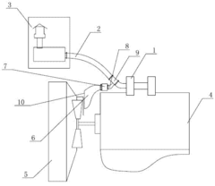
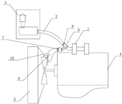
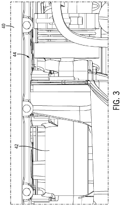
Device for increasing air intake flow of engine
PatentInactiveCN202065099U
Innovation
- A special-shaped pipe is set up behind the engine fan, and the wind generated by the fan is directed into the turbocharger through the air filter and corrugated hose to increase the engine air intake. Fluid mechanics is used to optimize the shape of the pipe to reduce air flow separation and noise.
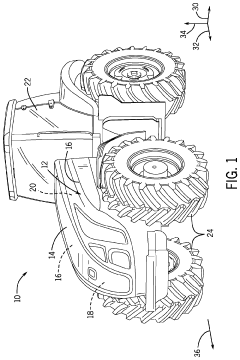
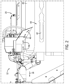
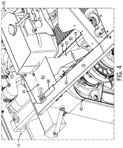
Engine airflow adjustment system
PatentActiveUS10688861B1
Innovation
- An engine airflow adjustment system that includes a funnel to redirect and focus airflow from the engine fan to specific locations, using angled sidewalls and a front wall to concentrate airflow and prevent debris from settling or becoming lodged in crevices, thereby blocking and removing debris from these areas.
Emissions Compliance Considerations
Enhancing airflow in the LS1 engine must be carefully balanced with emissions compliance requirements, as modifications that increase performance often impact exhaust emissions. The Environmental Protection Agency (EPA) and California Air Resources Board (CARB) regulations establish strict limits on vehicle emissions, with particular focus on nitrogen oxides (NOx), carbon monoxide (CO), hydrocarbons (HC), and particulate matter. Any airflow enhancement technique must ensure the engine remains within these regulatory boundaries.
Aftermarket modifications to intake and exhaust systems typically require certification to demonstrate compliance. CARB Executive Orders are particularly important for vehicles operated in California and states following CARB standards. Without proper certification, airflow modifications may be considered tampering with emissions control devices, potentially resulting in significant fines for both manufacturers and vehicle owners.
The oxygen sensor feedback system plays a critical role in emissions compliance when implementing airflow enhancements. Modified air-fuel ratios must remain within the operational parameters of the engine management system to maintain proper catalytic converter function. Excessively lean mixtures can increase NOx emissions, while rich mixtures elevate HC and CO levels. Advanced tuning solutions often incorporate wide-band oxygen sensors to maintain optimal air-fuel ratios across the enhanced airflow range.
Catalytic converter efficiency must be preserved when implementing airflow modifications. Higher exhaust gas temperatures resulting from increased airflow can potentially damage catalysts or reduce their operational lifespan. Some high-performance applications utilize high-flow catalytic converters that maintain emissions compliance while reducing exhaust restriction, though these must still meet regulatory standards.
Positive Crankcase Ventilation (PCV) systems require special consideration when enhancing airflow. Modifications to intake manifolds or valve covers must maintain proper crankcase ventilation to prevent increased hydrocarbon emissions. Similarly, Exhaust Gas Recirculation (EGR) systems, which reduce NOx emissions by recirculating a portion of exhaust gases back into the combustion chamber, must remain functional after airflow modifications.
Evaporative emissions control systems can be affected by intake modifications that alter engine vacuum characteristics. Proper function of these systems is essential for emissions compliance, particularly in modern vehicles with enhanced evaporative emissions testing protocols. Modifications must ensure that purge and seal functions remain within specification.
For racing applications, it's worth noting that vehicles used exclusively for competition purposes may be exempt from certain emissions requirements. However, these exemptions typically apply only to dedicated race vehicles not operated on public roads, requiring careful documentation and compliance with specific regulatory provisions.
Performance Testing Methodologies
Performance testing methodologies for LS1 engine airflow enhancement techniques require systematic approaches to accurately measure and validate improvements. Flow bench testing represents the primary methodology, utilizing specialized equipment to measure airflow volume through cylinder heads at various valve lift points. This process typically involves maintaining a constant pressure differential (usually 28 inches of water) while recording cubic feet per minute (CFM) values. Modern digital flow benches provide comprehensive data including flow efficiency percentages and velocity profiles across the entire valve lift range.
Dynamometer testing serves as the definitive real-world validation method, measuring actual power and torque gains resulting from airflow modifications. Engine dynamometers provide controlled testing environments where variables such as air/fuel ratios, timing, and temperature can be precisely regulated. Chassis dynamometers, while introducing additional drivetrain variables, offer the advantage of testing the complete vehicle system under load conditions that more closely simulate real-world driving scenarios.
Computational Fluid Dynamics (CFD) analysis has emerged as a valuable pre-implementation testing methodology. Advanced software simulations model airflow patterns through intake manifolds, cylinder heads, and exhaust systems, allowing engineers to visualize turbulence, pressure zones, and flow characteristics without physical prototyping. This approach significantly reduces development time and costs while providing insights that would be difficult to obtain through traditional testing methods.
Pressure mapping techniques utilize specialized sensors placed at strategic points throughout the induction and exhaust systems to measure pressure differentials during engine operation. This methodology helps identify flow restrictions and optimization opportunities by creating detailed pressure maps that correlate with specific RPM ranges and load conditions.
A/B comparative testing methodology involves establishing baseline measurements before implementing modifications, then conducting identical tests after changes are made. This approach requires strict control of variables including ambient temperature, humidity, fuel quality, and engine operating temperature to ensure valid comparisons. Statistical analysis of multiple test runs helps eliminate anomalies and confirm the consistency of performance improvements.
Long-term durability testing must complement performance testing to ensure that airflow enhancements maintain their effectiveness over time and do not compromise engine reliability. This typically involves extended running periods under various load conditions, followed by inspection and re-testing to verify consistent performance characteristics.
Unlock deeper insights with Patsnap Eureka Quick Research — get a full tech report to explore trends and direct your research. Try now!
Generate Your Research Report Instantly with AI Agent
Supercharge your innovation with Patsnap Eureka AI Agent Platform!