

LS1 Engine Intake Flow Testing
AUG 25, 20259 MIN READ
Generate Your Research Report Instantly with AI Agent
PatSnap Eureka helps you evaluate technical feasibility & market potential.
LS1 Engine Intake Flow Background & Objectives
The LS1 engine, introduced by General Motors in 1997, marked a significant evolution in the small-block V8 engine family. This revolutionary powerplant featured an aluminum block and heads, reducing weight while maintaining exceptional durability. The intake flow characteristics of the LS1 became a focal point for performance enthusiasts and engineers alike, as optimizing airflow represents one of the most cost-effective methods to increase engine power and efficiency.
Historically, intake flow testing has evolved from rudimentary visual smoke tests to sophisticated digital flow benches capable of measuring airflow volume, velocity, and patterns with remarkable precision. The development of computational fluid dynamics (CFD) in the 1980s and 1990s further revolutionized how engineers understand and optimize intake systems, though physical testing remains essential for validation.
The primary objective of LS1 intake flow testing is to quantify and analyze the volumetric efficiency of the intake system under various operating conditions. This includes measuring airflow rates through intake ports at different valve lift positions, identifying flow restrictions, and evaluating the effectiveness of port designs. Such testing provides critical data for optimizing cylinder head designs, intake manifold configurations, and overall engine breathing characteristics.
Current technological trends in this field include the integration of advanced sensors for real-time flow visualization, machine learning algorithms for predictive performance modeling, and rapid prototyping techniques that allow for iterative design improvements. The convergence of traditional flow bench testing with computational simulation has created a hybrid approach that yields more comprehensive results than either method alone.
The significance of intake flow testing extends beyond raw performance gains. As emissions regulations become increasingly stringent worldwide, optimizing combustion efficiency through improved intake flow characteristics represents a crucial strategy for meeting environmental standards while maintaining or enhancing performance. Additionally, the knowledge gained from LS1 testing has broad applications across GM's engine portfolio and influences industry-wide design practices.
The technical goals for LS1 intake flow testing typically include identifying the optimal port geometry for maximum flow efficiency, determining the ideal valve size and lift profiles, evaluating the effects of various intake manifold designs, and understanding the dynamic airflow characteristics under simulated operating conditions. These objectives support both immediate performance enhancement and long-term engine development strategies.
Market Analysis for LS1 Performance Enhancement
The LS1 performance enhancement market has experienced significant growth over the past decade, driven by enthusiasts seeking to maximize the potential of their GM LS1 engines. This market segment represents a substantial portion of the overall automotive aftermarket industry, which was valued at approximately $45 billion in 2022. Within this broader market, the performance intake system segment accounts for roughly $1.2 billion annually, with LS1-specific components representing about 15% of this subsegment.
Consumer demand for LS1 performance enhancements is primarily fueled by three distinct customer segments. First, traditional muscle car enthusiasts who own vehicles originally equipped with the LS1 engine (1997-2004 Corvettes, 1998-2002 Camaros/Firebirds) seeking to restore and enhance their vehicles. Second, modern performance enthusiasts who retrofit LS1 engines into various platforms due to their excellent power-to-weight ratio and modification potential. Third, competitive motorsport participants who require maximum performance within specific rule constraints.
Market research indicates that intake flow optimization represents one of the highest ROI modifications available for LS1 engines, with typical gains of 15-25 horsepower achievable through properly engineered intake systems. This has created a specialized market for flow testing services and optimized intake components, with annual growth rates exceeding 8% since 2018.
Regional analysis shows particularly strong demand in the Southern and Western United States, with Texas, California, and Florida representing the largest state markets. Internationally, Australia has emerged as a significant market due to their strong V8 culture and the popularity of Holden vehicles equipped with LS1 derivatives.
Price sensitivity varies significantly by customer segment. Professional racing teams demonstrate low price sensitivity, prioritizing performance gains regardless of cost. Enthusiast consumers show moderate price sensitivity, typically willing to pay premium prices only when performance benefits are clearly demonstrated through verifiable testing data. Budget-conscious consumers represent a growing segment, seeking entry-level performance enhancements with demonstrable value.
Market forecasts project continued growth in the LS1 performance sector despite the engine's discontinued production status. This paradoxical trend is supported by the engine's widespread availability in salvage markets, continued parts support from GM, and the development of modernized variants (LS2, LS3, etc.) that share many architectural characteristics with the original LS1, allowing for knowledge and technology transfer across platforms.
Current Intake Flow Testing Challenges
Despite significant advancements in intake flow testing methodologies for LS1 engines, several persistent challenges continue to impede accurate performance evaluation and optimization. Traditional flow bench testing, while established, suffers from notable limitations in replicating real-world dynamic conditions. Static flow measurements fail to capture the complex pulsation effects and pressure wave dynamics that occur during actual engine operation, leading to potential discrepancies between bench test results and real-world performance.
Measurement consistency remains problematic across different testing facilities and equipment configurations. Variations in test procedures, equipment calibration, and environmental conditions can result in flow coefficient disparities of up to 8-12% for identical intake components. This inconsistency complicates cross-comparison of data and creates challenges for engineers attempting to validate design improvements.
The industry also faces significant challenges in standardization. Current testing protocols exhibit considerable variation in measurement techniques, reference pressures, and correction factors. The absence of universally accepted standards for LS1 intake flow testing makes it difficult to establish reliable benchmarks and compare results across different research institutions and performance shops.
Modern LS1 intake designs incorporate increasingly complex geometries, including variable runner lengths, tuned resonance chambers, and intricate port shapes. These sophisticated designs create measurement challenges that conventional flow testing equipment struggles to accurately characterize. Traditional flow benches may not adequately capture the performance benefits of these advanced design features, particularly at varying RPM ranges.
Computational limitations present another significant hurdle. While Computational Fluid Dynamics (CFD) offers promising alternatives to physical testing, current simulation models still struggle to perfectly replicate the complex turbulent flow patterns and boundary layer behaviors within intake systems. The computational resources required for high-fidelity simulations remain prohibitively expensive for many development teams.
Temperature-related testing challenges persist as well. Most flow bench testing occurs at ambient temperatures, failing to account for the thermal expansion and material property changes that occur at operating temperatures. This discrepancy can lead to meaningful differences between tested flow characteristics and actual performance under normal engine operating conditions.
Finally, the correlation between static flow numbers and actual engine performance continues to be imperfectly understood. High flow numbers on a bench test do not always translate directly to improved horsepower or torque across the entire RPM range, highlighting the need for more sophisticated testing methodologies that better predict real-world performance outcomes.
Current LS1 Intake Flow Testing Solutions
01 Intake manifold design for improved flow
The design of intake manifolds significantly impacts the airflow into LS1 engines. Optimized manifold geometry, including runner length, cross-sectional area, and plenum volume, can enhance air delivery to the cylinders. Advanced designs incorporate smooth transitions and flow-optimized pathways to reduce turbulence and pressure drops, resulting in improved volumetric efficiency and engine performance.- Intake manifold design for improved flow: The design of intake manifolds significantly impacts the airflow into LS1 engines. Optimized manifold geometry, including runner length, cross-sectional area, and plenum volume, can enhance air delivery to the cylinders. Advanced designs incorporate smooth transitions and flow-optimized pathways to reduce turbulence and pressure drops, resulting in improved volumetric efficiency and engine performance.
- Air flow measurement and control systems: Various systems for measuring and controlling air flow in LS1 engine intakes help optimize performance. These include mass airflow sensors, pressure sensors, and electronic control units that adjust intake parameters based on operating conditions. Advanced systems can dynamically modify intake characteristics to match engine demands across different RPM ranges and load conditions, improving both power output and fuel efficiency.
- Intake valve and port optimization: The design of intake valves and ports plays a crucial role in LS1 engine airflow. Optimized valve timing, lift profiles, and port geometry can significantly enhance the volume and velocity of air entering the combustion chamber. Techniques such as port matching, valve seat profiling, and multi-valve configurations are employed to reduce flow restrictions and improve cylinder filling at various engine speeds.
- Forced induction systems for LS1 engines: Forced induction systems such as turbochargers and superchargers can dramatically increase airflow into LS1 engines. These systems compress intake air, increasing its density and allowing more oxygen to enter the combustion chamber. Design considerations include intercooling, boost control, and integration with the existing intake system to maintain proper air-fuel ratios and prevent engine damage while significantly enhancing power output.
- Air filtration and intake tract optimization: The design of air filtration systems and intake tracts affects the quality and quantity of air flowing into LS1 engines. Cold air intakes, resonator removal, and streamlined air box designs can reduce restriction while maintaining adequate filtration. Optimizing the entire intake path from air entry to the throttle body minimizes pressure drops and turbulence, allowing for smoother, more efficient airflow and improved engine breathing.
02 Air flow measurement and control systems
Various systems for measuring and controlling air flow in LS1 engine intakes help optimize performance. These include mass airflow sensors, pressure sensors, and electronic control units that adjust intake parameters based on operating conditions. Advanced systems can dynamically modify intake characteristics to match engine demands across different RPM ranges and load conditions.Expand Specific Solutions03 Intake valve and port optimization
Optimization of intake valves and ports is crucial for maximizing airflow into LS1 engine cylinders. This includes valve timing, lift profiles, and port geometry design. Improved valve designs with better flow coefficients and port shapes that reduce flow separation can significantly enhance the breathing capability of the engine, leading to increased power output and efficiency.Expand Specific Solutions04 Forced induction and intake pressure enhancement
Forced induction systems such as turbochargers and superchargers can dramatically increase the intake air pressure and density in LS1 engines. These systems compress incoming air, allowing more oxygen to enter the combustion chamber for improved power output. Design considerations include intercooling, boost control, and integration with the existing intake system to maintain proper air-fuel ratios and prevent engine damage.Expand Specific Solutions05 Air filtration and intake air conditioning
Air filtration systems and intake air conditioning play important roles in LS1 engine performance. Effective filtration removes contaminants that could damage engine components while minimizing flow restriction. Intake air conditioning, including cooling and humidity control, can increase air density and reduce intake air temperature, resulting in improved combustion efficiency and power output.Expand Specific Solutions
Major Players in Engine Development Industry
The LS1 Engine Intake Flow Testing market is in a growth phase, with increasing demand driven by automotive manufacturers seeking performance optimization. The market size is expanding due to the rising focus on engine efficiency and emissions reduction. Technologically, the field is moderately mature but evolving, with companies like Robert Bosch, Volkswagen AG, and BMW leading innovation through advanced flow measurement techniques and computational fluid dynamics. Nissan, Honda, and Mercedes-Benz are investing in sophisticated testing methodologies, while Vitesco Technologies and Weichai Power are developing specialized intake flow optimization solutions. Academic institutions like Tianjin University and Jilin University contribute valuable research, creating a competitive landscape where collaboration between industry and academia drives technological advancement in engine breathing efficiency.
Robert Bosch GmbH
Technical Solution: Bosch has developed advanced LS1 engine intake flow testing systems that utilize high-precision digital flow measurement technology combined with computational fluid dynamics (CFD) simulation. Their approach integrates real-time data acquisition systems with multi-point pressure and temperature sensors throughout the intake tract. Bosch's testing methodology incorporates both steady-state and transient flow analysis capabilities, allowing for comprehensive evaluation of intake port efficiency, swirl generation, and flow distribution across various engine operating conditions. Their systems feature automated valve lift control mechanisms that can simulate actual engine operation while measuring volumetric efficiency and flow coefficients with precision typically within ±0.5% margin of error.
Strengths: Industry-leading sensor integration and data acquisition capabilities; comprehensive testing methodology covering both steady-state and transient conditions. Weaknesses: Higher implementation costs compared to simpler testing solutions; requires specialized technical expertise to fully utilize advanced features.
Beijing Foton Cummins Engine Co., Ltd.
Technical Solution: Beijing Foton Cummins has developed a specialized LS1 engine intake flow testing platform that combines traditional flow bench methodologies with advanced digital modeling. Their system utilizes a proprietary flow coefficient calculation algorithm that accounts for the unique characteristics of heavy-duty diesel engine applications. The testing protocol incorporates variable pressure differential measurements across multiple valve lift positions, with particular emphasis on optimizing intake port geometry for improved combustion efficiency. Their approach includes correlation studies between flow bench results and dynamometer performance data, establishing direct relationships between intake flow characteristics and engine power output, fuel efficiency, and emissions performance in real-world operating conditions.
Strengths: Strong correlation between bench testing and real-world engine performance; specialized expertise in heavy-duty diesel applications. Weaknesses: Testing methodology may be less applicable to smaller displacement gasoline engines; limited focus on transient flow conditions.
Key Technical Innovations in Flow Bench Testing
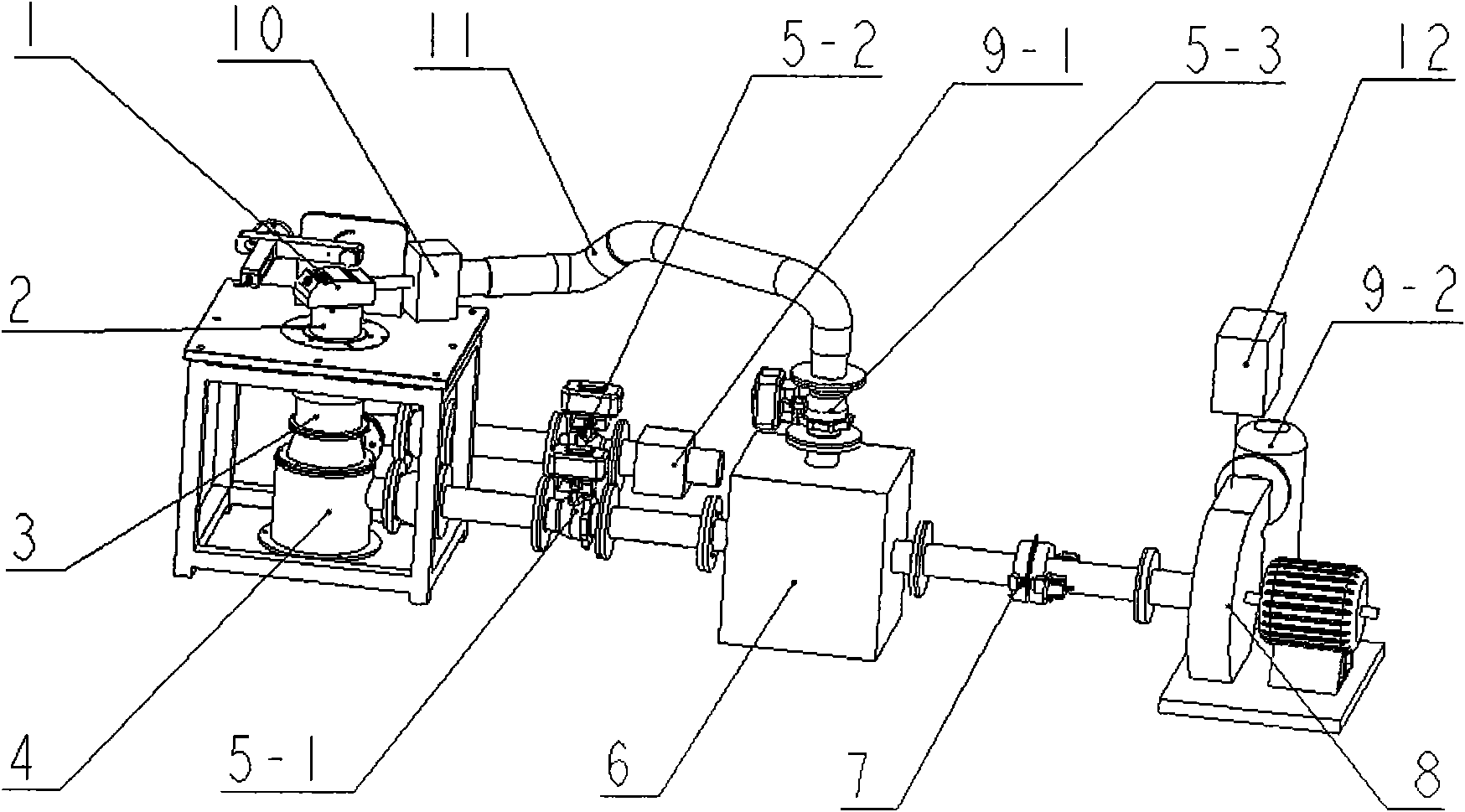
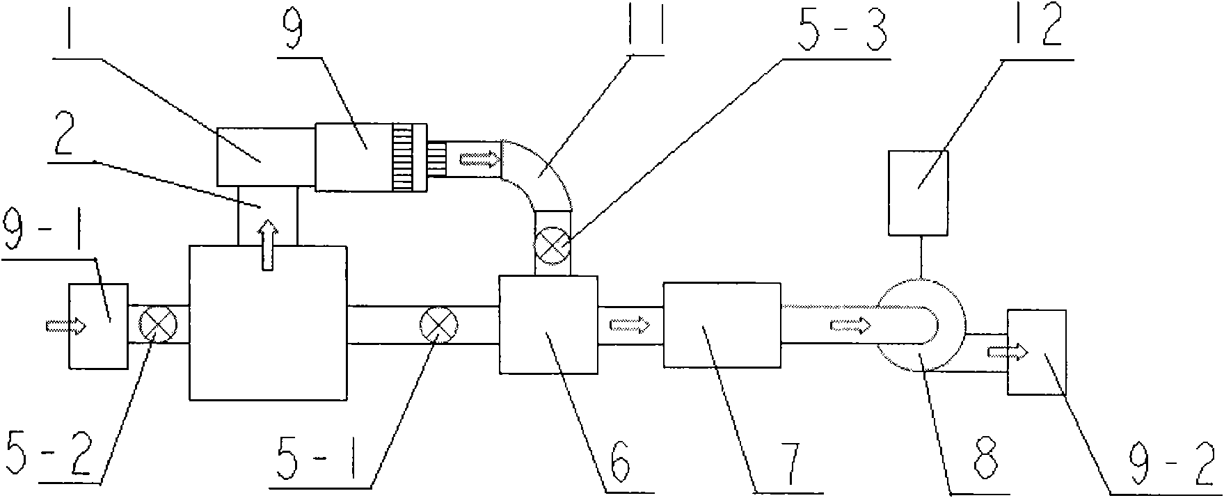
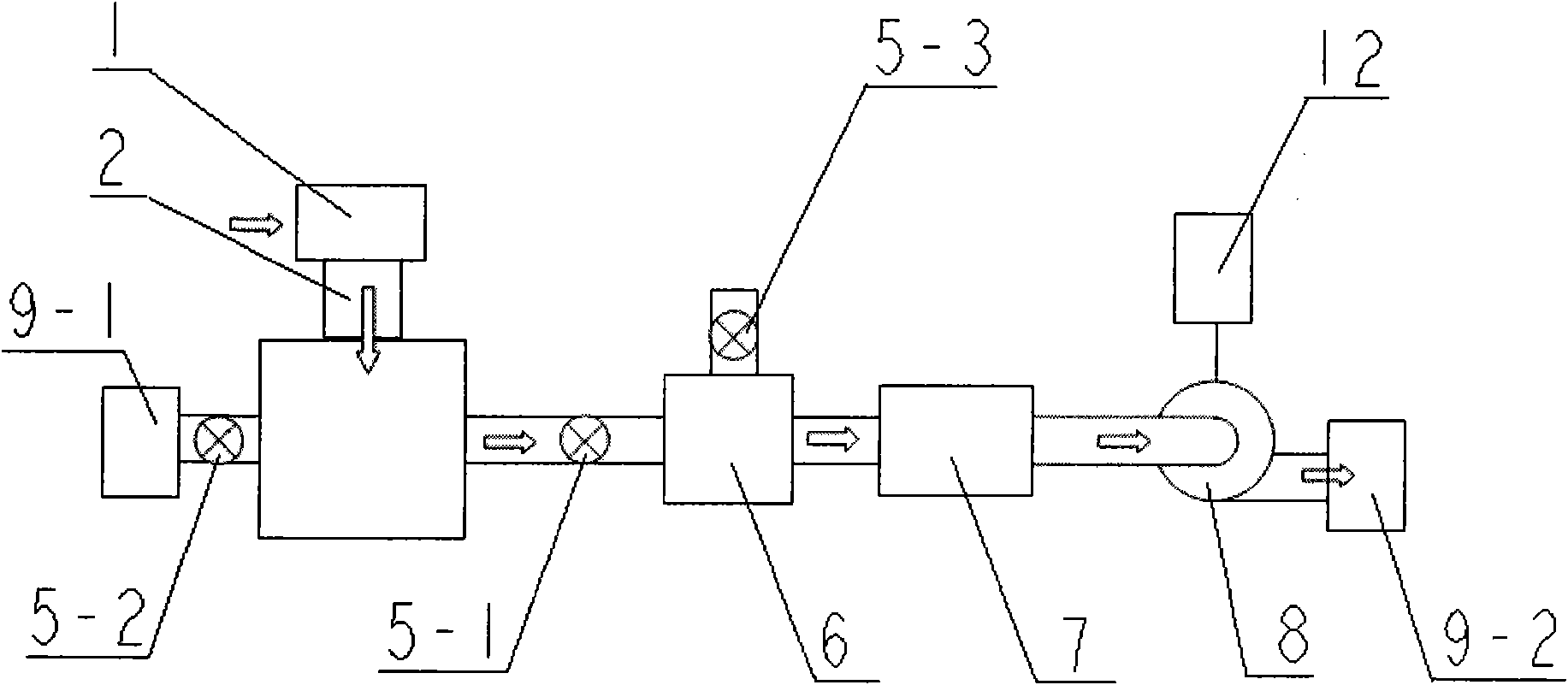
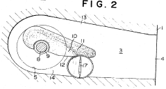
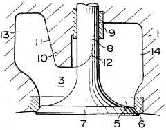
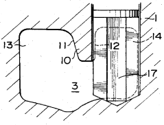
Testing device for quickly detecting flow property parameters of air passage of internal combustion engine
PatentActiveCN101655413A
Innovation
- A test device is designed to quickly detect the flow performance parameters of the internal combustion engine airway, using cylinder liners, momentum meters, pressure stabilizing barrels, electric ball valves, pressure stabilizing boxes, air filters, flow meters, induced draft fans, frequency converters and airflow combers. The frequency converter adjusts the speed of the induced draft fan to keep the airway pressure difference constant, eliminating the need to adjust the airway pressure difference and ensuring fully developed turbulent flow of gas in the cylinder liner.
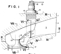
Method and system for controlling intake flow between direct and helical intake passages of intake port of internal combustion engine
PatentInactiveUS4527519A
Innovation
- A method and system that control the intake passage switchover valve to direct a minimum proportion of intake flow through the straight passage during idling and a maximum proportion through the helical passage for strong swirling, and vice versa during loaded operations, using temperature and load detection to adjust the valve position based on engine conditions.
Emissions Compliance Considerations
Emissions compliance represents a critical consideration in LS1 engine intake flow testing, as regulatory frameworks continue to evolve with increasingly stringent standards worldwide. The intake system design directly impacts combustion efficiency, fuel mixture quality, and ultimately the emissions profile of the engine. Testing must account for both current regulatory requirements and anticipated future standards to ensure long-term viability of engine designs.
The LS1 intake flow characteristics significantly influence emissions of nitrogen oxides (NOx), carbon monoxide (CO), unburned hydrocarbons (HC), and particulate matter. Flow testing methodologies must incorporate measurement protocols that can accurately predict real-world emissions performance under various operating conditions. This includes evaluation across different load profiles, temperature ranges, and altitude variations that might affect emissions compliance.
Modern emissions regulations such as Euro 6d, EPA Tier 3, and California's CARB standards impose specific limits that directly influence intake design parameters. Flow testing must therefore incorporate simulation of various driving cycles (WLTP, FTP-75, etc.) to ensure compliance across the full spectrum of engine operation. The correlation between intake flow characteristics and emissions output requires sophisticated modeling techniques that can translate flow bench data into predictive emissions performance.
On-board diagnostics (OBD) requirements further complicate emissions compliance considerations, as intake flow anomalies must be detectable through the vehicle's diagnostic systems. Flow testing protocols should therefore include evaluation of sensor placement and response characteristics to ensure proper monitoring capability throughout the engine's service life.
Cold-start emissions present particular challenges for intake system design, as flow characteristics change significantly during warm-up periods. Testing methodologies must account for these transient conditions, evaluating how intake geometry affects mixture formation and combustion stability during the critical first minutes of operation when catalytic converters have not reached operating temperature.
Advanced intake technologies such as variable geometry systems, resonance tuning, and integrated thermal management must be evaluated not only for performance benefits but also for their emissions impact. Flow testing should quantify how these technologies modify emissions profiles across the operating range, particularly during mode transitions that often represent emissions compliance challenges.
The increasing focus on real driving emissions (RDE) testing has expanded the operational envelope that intake systems must accommodate while maintaining emissions compliance. Flow testing protocols must therefore evolve to incorporate a wider range of conditions than traditional laboratory cycles, ensuring that intake performance remains optimal under actual driving scenarios.
Computational Fluid Dynamics Integration
Computational Fluid Dynamics (CFD) has revolutionized the approach to LS1 engine intake flow testing by providing sophisticated virtual simulation capabilities that complement traditional physical testing methods. The integration of CFD technology into the intake flow analysis workflow enables engineers to visualize and quantify complex airflow patterns that would be difficult or impossible to observe through conventional testing alone.
Modern CFD software packages such as ANSYS Fluent, STAR-CCM+, and OpenFOAM have been specifically adapted for automotive applications, offering specialized modules for internal combustion engine simulation. These tools can accurately model the transient, turbulent flow characteristics within the LS1 intake manifold, runners, and ports while accounting for compressibility effects and heat transfer phenomena.
The workflow for CFD integration typically begins with the creation of a detailed 3D model of the LS1 intake system, often derived from CAD data or 3D scanning of physical components. This geometry is then processed through meshing algorithms that divide the flow domain into millions of discrete cells where the governing Navier-Stokes equations are solved iteratively. For LS1 intake applications, adaptive mesh refinement techniques are particularly valuable in regions of high velocity gradients or complex geometry.
Boundary conditions for the simulation must be carefully defined to match real-world testing scenarios, including pressure differentials, temperature conditions, and wall surface characteristics. Advanced turbulence models such as k-ε, k-ω SST, or Large Eddy Simulation (LES) are employed to capture the complex flow behavior within the intake system. The selection of an appropriate turbulence model significantly impacts simulation accuracy and computational requirements.
Validation of CFD results against physical flow bench data remains essential for establishing simulation credibility. Research indicates that properly calibrated CFD models can achieve correlation within 3-5% of flow bench measurements for LS1 intake systems. This validation process typically involves comparing mass flow rates, pressure distributions, and flow coefficients between simulated and measured data points.
The computational demands of high-fidelity intake flow simulations have been addressed through parallel processing capabilities and cloud computing resources. Modern CFD implementations can distribute calculations across multiple CPU cores or GPU accelerators, reducing simulation time from days to hours for complex LS1 intake geometries. This efficiency gain has made iterative design optimization practical within development timelines.
Recent advancements in CFD integration include automated optimization algorithms that can systematically modify intake geometry parameters to maximize flow efficiency. These tools employ techniques such as genetic algorithms or adjoint-based methods to explore the design space and identify optimal configurations with minimal human intervention, significantly accelerating the development cycle for enhanced LS1 intake systems.
Unlock deeper insights with PatSnap Eureka Quick Research — get a full tech report to explore trends and direct your research. Try now!
Generate Your Research Report Instantly with AI Agent
Supercharge your innovation with PatSnap Eureka AI Agent Platform!