

Minimizing Voltage Drops in Source Inverter Systems
MAR 10, 20269 MIN READ
Generate Your Research Report Instantly with AI Agent
PatSnap Eureka helps you evaluate technical feasibility & market potential.
Inverter Voltage Drop Background and Technical Objectives
Source inverter systems have emerged as critical components in modern power electronics, serving as the backbone for renewable energy integration, electric vehicle charging infrastructure, and industrial motor drives. These systems convert direct current (DC) power sources into alternating current (AC) output, enabling efficient power delivery across diverse applications. However, voltage drops within inverter systems represent a persistent challenge that significantly impacts overall system efficiency, power quality, and operational reliability.
The evolution of inverter technology has been driven by the increasing demand for higher power densities, improved efficiency ratings, and enhanced grid integration capabilities. Early inverter designs primarily focused on basic DC-to-AC conversion functionality, but contemporary systems must address complex requirements including harmonic distortion minimization, grid synchronization, and fault tolerance. As power electronic devices have advanced from silicon-based semiconductors to wide-bandgap materials like silicon carbide and gallium nitride, new opportunities have emerged to address voltage drop challenges through innovative circuit topologies and control strategies.
Voltage drops in source inverter systems manifest through multiple pathways, including semiconductor conduction losses, parasitic resistances in interconnections, magnetic component losses, and switching transients. These voltage drops directly translate to power losses, reduced system efficiency, and potential thermal management issues. In high-power applications, even marginal voltage drops can result in substantial energy losses and economic impacts, making voltage drop minimization a critical design objective.
The primary technical objective centers on developing comprehensive strategies to minimize voltage drops while maintaining system stability, power quality, and cost-effectiveness. This encompasses optimizing semiconductor selection and gate drive circuits, implementing advanced pulse width modulation techniques, and designing low-impedance power delivery networks. Additionally, the integration of real-time monitoring and adaptive control algorithms represents a key objective for dynamic voltage drop compensation.
Secondary objectives include establishing standardized measurement methodologies for voltage drop characterization, developing predictive models for voltage drop behavior under varying load conditions, and creating design guidelines that balance voltage drop minimization with other performance parameters such as electromagnetic interference and thermal management. These objectives collectively aim to advance the state-of-the-art in inverter system design while addressing practical implementation challenges in commercial applications.
Market Demand for High-Efficiency Inverter Systems
The global power electronics market is experiencing unprecedented growth driven by the increasing demand for energy-efficient solutions across multiple sectors. High-efficiency inverter systems have emerged as critical components in renewable energy integration, electric vehicle infrastructure, and industrial automation applications. The transition toward sustainable energy sources has created substantial market opportunities for advanced inverter technologies that can minimize power losses and maximize system performance.
Renewable energy installations, particularly solar photovoltaic and wind power systems, represent the largest market segment driving demand for high-efficiency inverters. Grid-tied inverters must maintain optimal power conversion efficiency while ensuring stable grid integration and compliance with stringent power quality standards. The growing emphasis on distributed energy resources and microgrids has further amplified the need for inverter systems capable of operating with minimal voltage drops and maximum power throughput.
Electric vehicle charging infrastructure constitutes another rapidly expanding market segment requiring advanced inverter technologies. Fast-charging stations demand high-power inverter systems that can deliver consistent performance while minimizing energy losses during power conversion. The automotive industry's shift toward electrification has created substantial demand for onboard inverters that can operate efficiently across wide voltage and frequency ranges while maintaining compact form factors.
Industrial automation and motor drive applications continue to drive steady demand for high-efficiency inverter systems. Manufacturing facilities increasingly require variable frequency drives and servo systems that can deliver precise control while minimizing energy consumption. The focus on reducing operational costs and meeting environmental regulations has intensified the demand for inverter technologies that can achieve superior efficiency ratings.
Data center and telecommunications infrastructure represent emerging market segments with stringent efficiency requirements. Uninterruptible power supply systems and power conditioning equipment must operate with minimal losses to reduce cooling requirements and operational expenses. The exponential growth in cloud computing and digital services has created substantial demand for highly efficient power conversion systems.
Market dynamics indicate strong preference for inverter systems that can demonstrate measurable improvements in overall system efficiency and reliability. End users increasingly evaluate total cost of ownership rather than initial capital expenditure, creating opportunities for advanced technologies that can deliver superior long-term performance through reduced voltage drops and enhanced power conversion efficiency.
Current Voltage Drop Issues and Technical Challenges
Source inverter systems face significant voltage drop challenges that directly impact their operational efficiency and power quality. These voltage drops manifest across multiple system components, including power semiconductor devices, interconnecting conductors, filtering elements, and switching networks. The cumulative effect of these drops reduces the effective output voltage delivered to loads, compromising system performance and energy conversion efficiency.
Power semiconductor switches, particularly IGBTs and MOSFETs, contribute substantially to voltage drops through their inherent forward voltage characteristics. During conduction periods, these devices exhibit voltage drops ranging from 0.7V to 3V depending on current levels and device specifications. The switching frequency and duty cycle variations further exacerbate these losses, creating dynamic voltage drop patterns that challenge system stability.
Interconnecting conductors and bus bar systems present another critical voltage drop source. High-frequency switching currents generate significant resistive and inductive voltage drops across these pathways. The skin effect at elevated frequencies increases effective resistance, while parasitic inductances create additional voltage drops during current transitions. These effects become particularly pronounced in high-power applications where current magnitudes reach hundreds of amperes.
Filtering components, essential for harmonic mitigation, introduce their own voltage drop mechanisms. Inductor series resistance creates continuous voltage drops proportional to load current, while capacitor equivalent series resistance generates frequency-dependent losses. The interaction between these passive components and switching harmonics creates complex voltage drop profiles that vary with operating conditions.
Thermal effects compound voltage drop issues significantly. Rising junction temperatures in semiconductor devices increase forward voltage drops, creating positive feedback loops that further elevate temperatures. This thermal-electrical coupling reduces system efficiency and threatens component reliability, particularly under sustained high-power operation.
Grid integration challenges introduce additional voltage drop complexities. Power factor variations, harmonic distortion, and grid impedance interactions create dynamic voltage drop scenarios that traditional compensation methods struggle to address. The increasing penetration of renewable energy sources with variable output characteristics further complicates voltage regulation requirements.
Current measurement and control system limitations hinder effective voltage drop mitigation. Sensor accuracy, processing delays, and control algorithm constraints prevent real-time compensation of rapidly changing voltage drop conditions. These limitations become critical barriers in applications requiring precise voltage regulation and fast dynamic response.
Existing Solutions for Voltage Drop Minimization
01 Voltage compensation and regulation techniques in inverter systems
Various methods are employed to compensate for voltage drops in source inverter systems through active regulation and control strategies. These techniques involve monitoring the output voltage and adjusting the inverter control parameters to maintain stable voltage levels despite load variations or input fluctuations. Feedback control loops and voltage sensing circuits are utilized to detect voltage deviations and implement corrective actions in real-time.- Voltage compensation and regulation techniques in inverter systems: Various methods are employed to compensate for voltage drops in source inverter systems through active regulation and control strategies. These techniques involve monitoring the output voltage and adjusting the inverter control parameters to maintain stable voltage levels despite load variations or input fluctuations. Feedback control loops and voltage sensing circuits are utilized to detect voltage deviations and implement corrective actions in real-time.
- Power factor correction and reactive power management: Addressing voltage drops through power factor correction methods helps minimize losses in inverter systems. These approaches involve controlling the phase relationship between voltage and current to reduce reactive power consumption. By optimizing power factor, the system can maintain better voltage stability and reduce the impact of voltage drops across transmission lines and components.
- Multi-level inverter topologies for voltage stability: Advanced inverter configurations utilizing multiple voltage levels provide improved voltage regulation and reduced harmonic distortion. These topologies create stepped voltage waveforms that more closely approximate sinusoidal output, resulting in better voltage quality and reduced stress on components. The multi-level approach also allows for better distribution of voltage stress across switching devices.
- Cable and conductor impedance compensation: Techniques for mitigating voltage drops caused by cable resistance and inductance in the distribution path between the inverter and load. These methods include impedance calculation algorithms and adaptive control strategies that account for the electrical characteristics of conductors. Compensation mechanisms adjust the inverter output to counteract the expected voltage drop based on load current and cable parameters.
- Load-adaptive voltage boost and droop control: Dynamic voltage adjustment strategies that respond to load changes by implementing boost or droop characteristics to maintain voltage within acceptable ranges. These control methods predict or measure load-induced voltage variations and preemptively adjust the inverter output voltage. The techniques enable the system to handle varying load conditions while minimizing voltage deviation at the point of use.
02 Power factor correction and reactive power management
Addressing voltage drops through power factor correction methods helps minimize losses in inverter systems. These approaches involve controlling the phase relationship between voltage and current to reduce reactive power consumption. By optimizing power factor, the system can reduce voltage drops across transmission lines and improve overall efficiency. Advanced control algorithms enable dynamic adjustment of reactive power to maintain voltage stability under varying load conditions.Expand Specific Solutions03 Cable and conductor impedance compensation
Techniques for mitigating voltage drops caused by cable resistance and inductance in inverter distribution systems are implemented through impedance compensation methods. These solutions account for the electrical characteristics of conductors and adjust the inverter output accordingly. Compensation algorithms calculate the expected voltage drop based on cable parameters and load current, then pre-emptively increase the output voltage to counteract these losses.Expand Specific Solutions04 Multi-level inverter topologies for voltage stability
Advanced inverter architectures utilizing multi-level configurations provide improved voltage regulation and reduced voltage drop characteristics. These topologies generate output voltages with multiple discrete levels, resulting in better waveform quality and reduced harmonic distortion. The multi-level approach allows for more precise voltage control and can better maintain output voltage under varying load conditions while minimizing switching losses.Expand Specific Solutions05 Load sensing and adaptive voltage control
Intelligent load monitoring systems detect changes in current demand and dynamically adjust inverter output voltage to compensate for anticipated voltage drops. These adaptive control strategies use predictive algorithms to anticipate voltage drop based on load characteristics and system parameters. Real-time sensing and processing enable rapid response to load transients, maintaining voltage within acceptable limits across various operating conditions.Expand Specific Solutions
Key Players in Power Electronics and Inverter Industry
The voltage drop minimization in source inverter systems represents a mature technology domain within the rapidly expanding power electronics market, valued at approximately $45 billion globally. The competitive landscape spans multiple development stages, from established automotive giants like Toyota, Honda, and GM implementing advanced inverter technologies in electric vehicles, to specialized power electronics companies such as SMA Solar Technology and ABB leading utility-scale applications. Technology maturity varies significantly across segments, with companies like Renesas Electronics, STMicroelectronics, and Intel driving semiconductor-level innovations, while Mitsubishi Electric and Schweitzer Engineering Laboratories focus on industrial automation solutions. The market demonstrates high fragmentation, encompassing traditional automotive manufacturers, semiconductor specialists, power system integrators, and emerging energy storage companies like Alelion Energy Systems, indicating both technological convergence and diverse application-specific optimization approaches across transportation, renewable energy, and industrial sectors.
SMA Solar Technology AG
Technical Solution: SMA Solar Technology implements advanced power electronics solutions featuring multi-level inverter topologies with optimized switching strategies to minimize voltage drops. Their technology incorporates dynamic voltage regulation algorithms that continuously monitor and adjust output parameters in real-time. The company utilizes high-efficiency SiC (Silicon Carbide) power semiconductors combined with sophisticated control systems that maintain voltage stability across varying load conditions. Their inverter systems feature integrated reactive power compensation and grid-tie capabilities that help stabilize voltage levels during power conversion processes.
Strengths: Industry-leading expertise in solar inverter technology with proven voltage regulation capabilities. Weaknesses: Solutions primarily focused on solar applications, limiting broader industrial applicability.
Intel Corp.
Technical Solution: Intel approaches voltage drop minimization through advanced digital signal processing and embedded control solutions for inverter systems. Their technology leverages high-performance microcontrollers and FPGAs that enable sophisticated real-time control algorithms for voltage regulation and power conversion optimization. The company's solutions include integrated communication capabilities that support smart grid applications and distributed inverter management. Intel's approach emphasizes software-defined power electronics with machine learning capabilities for predictive voltage control and system optimization, particularly targeting next-generation smart inverter applications in renewable energy and electric vehicle charging infrastructure.
Strengths: Advanced digital processing capabilities and software expertise enabling intelligent voltage control systems. Weaknesses: Limited direct power electronics experience compared to traditional inverter manufacturers, requiring partnerships for complete solutions.
Core Innovations in Low-Loss Inverter Design
Method and apparatus for minimising a circulating current or a common-mode voltage of an inverter
PatentActiveUS20150131345A1
Innovation
- Measuring common-mode voltage and controlling the cycle length of switching cycles in inverter bridges or active rectifier bridges to synchronize modulation patterns, thereby minimizing circulating currents without the need for communication links or current sensors.


Method and apparatus for active voltage control of electric motors
PatentActiveUS7843156B2
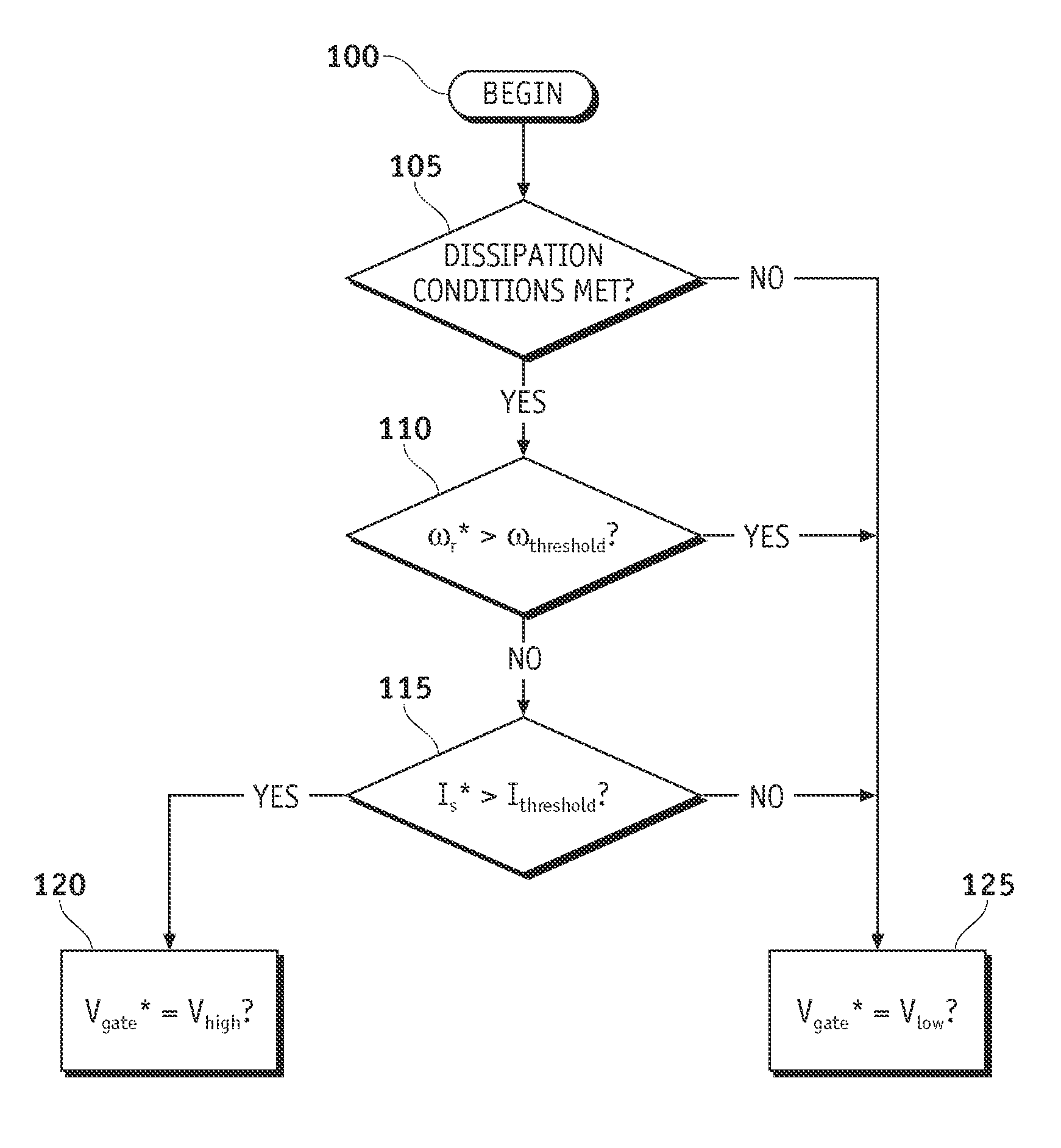
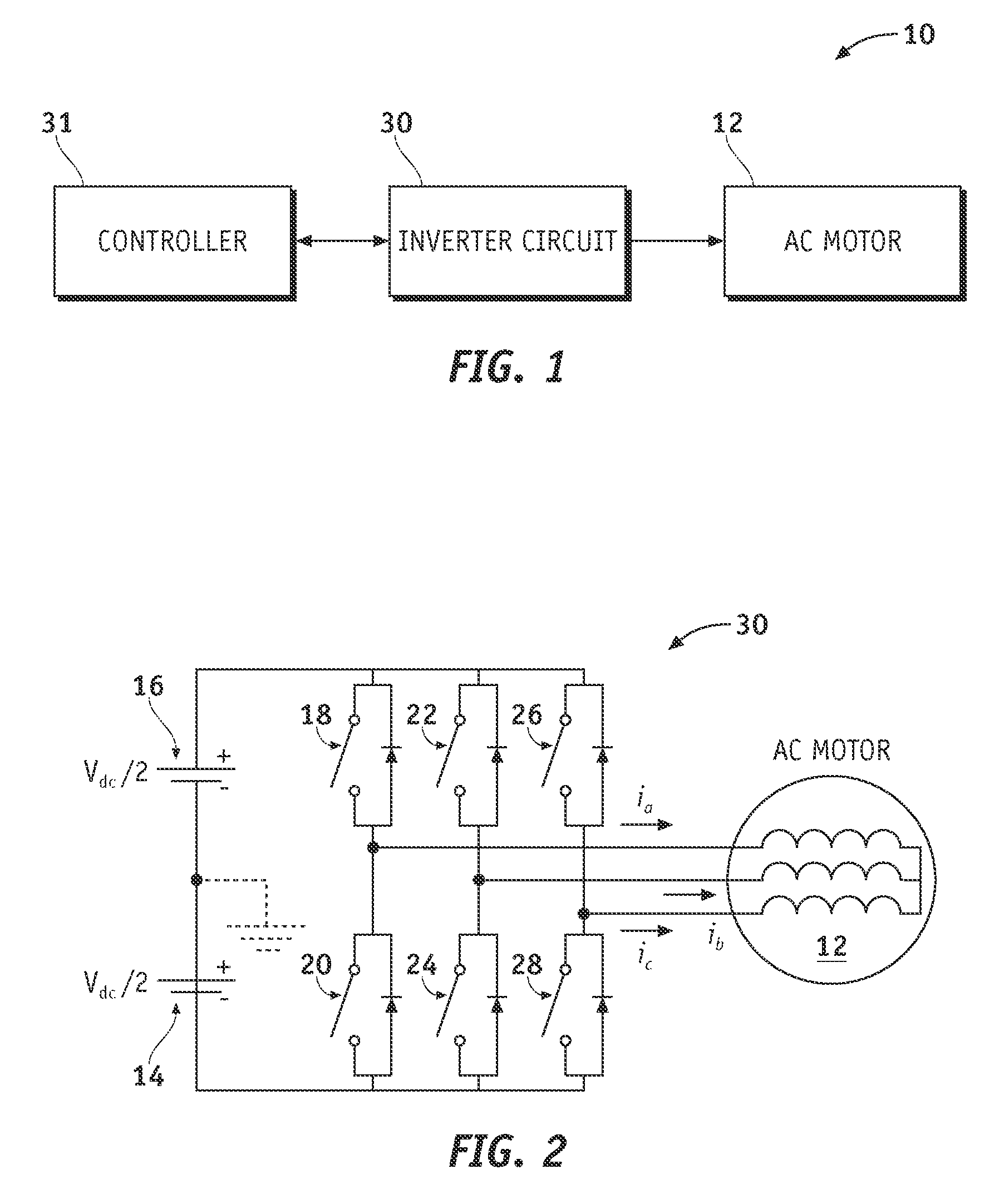
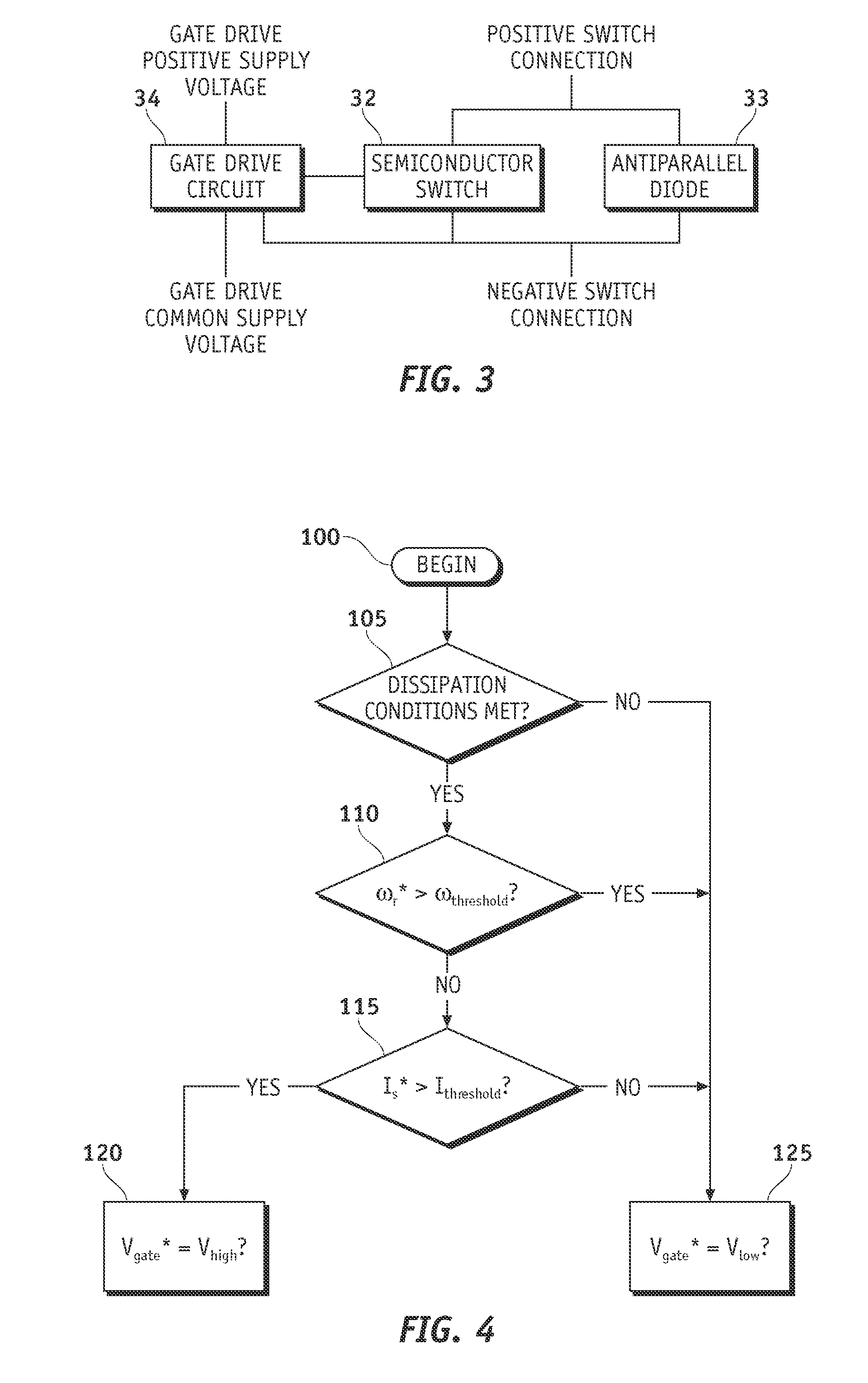
Innovation
- The method involves dynamically modifying the gate drive voltage based on the speed of the electric motor, increasing it during low-speed, high-current conditions to reduce conduction losses and support increased current-carrying capacity, while employing lower gate drive voltages during higher speeds and elevated voltage supply conditions to enhance operating margins.
Grid Code Compliance for Inverter Systems
Grid code compliance represents a fundamental requirement for inverter systems operating within electrical power networks, establishing the regulatory framework that governs how these systems must behave under various operating conditions. Modern grid codes have evolved significantly to address the increasing penetration of renewable energy sources and distributed generation systems, with particular emphasis on maintaining power quality and system stability.
The regulatory landscape for inverter-based systems encompasses multiple jurisdictions, each with specific requirements for voltage regulation, frequency response, and fault ride-through capabilities. Major grid codes such as IEEE 1547, IEC 61727, and regional standards like the European Network Code RfG define stringent parameters for voltage deviation limits, typically requiring inverters to operate within ±5% to ±10% of nominal voltage levels. These standards directly impact voltage drop minimization strategies, as non-compliance can result in system disconnection or curtailment.
Voltage quality requirements within grid codes specifically address issues related to voltage drops and fluctuations. Inverters must demonstrate capability to maintain output voltage within prescribed limits during normal operation and provide reactive power support during grid disturbances. The latest revisions of grid codes increasingly mandate advanced grid support functions, including voltage regulation through reactive power injection and dynamic voltage support during fault conditions.
Compliance verification processes require comprehensive testing protocols that validate inverter performance under various voltage scenarios. These include steady-state voltage regulation tests, dynamic response assessments during voltage sags, and verification of ride-through capabilities during extended voltage deviations. Testing standards such as UL 1741 SA and IEC 62116 provide detailed procedures for demonstrating compliance with voltage-related requirements.
The integration of smart inverter functionalities has introduced additional compliance considerations, particularly regarding autonomous voltage regulation and communication protocols. Grid codes now specify requirements for volt-VAR control, volt-watt control, and coordinated voltage regulation schemes that directly influence voltage drop mitigation strategies. These advanced functions must operate within defined response times and accuracy tolerances while maintaining system stability.
Emerging grid code developments reflect the evolving nature of power systems, with increasing emphasis on resilience and adaptive control capabilities. Future compliance frameworks are expected to incorporate more sophisticated voltage management requirements, including predictive control algorithms and enhanced coordination between multiple inverter systems to collectively address voltage drop challenges across distribution networks.
Thermal Management in High-Efficiency Inverters
Thermal management represents a critical engineering challenge in high-efficiency inverter systems, particularly when addressing voltage drop minimization. As inverters operate at higher efficiency levels, the concentrated heat generation from power semiconductor devices, magnetic components, and switching circuits creates thermal hotspots that can significantly impact system performance and reliability.
The relationship between thermal management and voltage drops is fundamentally interconnected through temperature-dependent electrical characteristics of power devices. Silicon carbide (SiC) and gallium nitride (GaN) semiconductors, commonly employed in high-efficiency inverters, exhibit varying on-resistance and forward voltage drops as junction temperatures fluctuate. Effective thermal control maintains these parameters within optimal ranges, directly contributing to voltage drop minimization objectives.
Advanced cooling architectures have evolved to address these thermal challenges. Liquid cooling systems utilizing microchannel heat exchangers provide superior heat dissipation capabilities compared to traditional air-cooling methods. These systems can maintain junction temperatures below 125°C even under high-power density operations, ensuring consistent electrical performance. Phase-change cooling technologies, including heat pipes and vapor chambers, offer enhanced thermal conductivity paths from heat sources to heat sinks.
Thermal interface materials (TIMs) play a crucial role in heat transfer efficiency between semiconductor packages and cooling systems. Modern TIMs incorporating graphene composites and metal-filled polymers achieve thermal conductivities exceeding 10 W/mK, significantly reducing thermal resistance in the heat transfer path. Proper TIM selection and application techniques directly influence the thermal performance of high-power inverter modules.
Smart thermal management strategies integrate real-time temperature monitoring with adaptive control algorithms. These systems dynamically adjust switching frequencies, modulation schemes, and power distribution based on thermal feedback, preventing thermal runaway conditions while maintaining optimal efficiency. Temperature sensors embedded within power modules provide precise thermal data for predictive maintenance and performance optimization.
Packaging innovations contribute substantially to thermal management effectiveness. Direct bonded copper (DBC) substrates and advanced wire bonding techniques reduce thermal resistance between semiconductor dies and external cooling systems. Three-dimensional packaging approaches distribute heat sources more effectively, preventing localized thermal concentrations that could compromise voltage stability and system reliability in high-efficiency inverter applications.
Unlock deeper insights with PatSnap Eureka Quick Research — get a full tech report to explore trends and direct your research. Try now!
Generate Your Research Report Instantly with AI Agent
Supercharge your innovation with PatSnap Eureka AI Agent Platform!