

Developer supply container with mounting attitude regulation and drive receiving member rotation suppression features
a technology of development supply and attitude regulation, applied in the field of development supply containers, can solve the problems of affecting the operation the deterioration of the durability of the gear, and the occurrence of toner scattering around, so as to achieve the effect of suppressing the deterioration of the development supply container
Patent Information
- Authority / Receiving Office
- US · United States
- Patent Type
- Patents(United States)
- Current Assignee / Owner
- Publication Date
- 2012-05-29
Smart Images
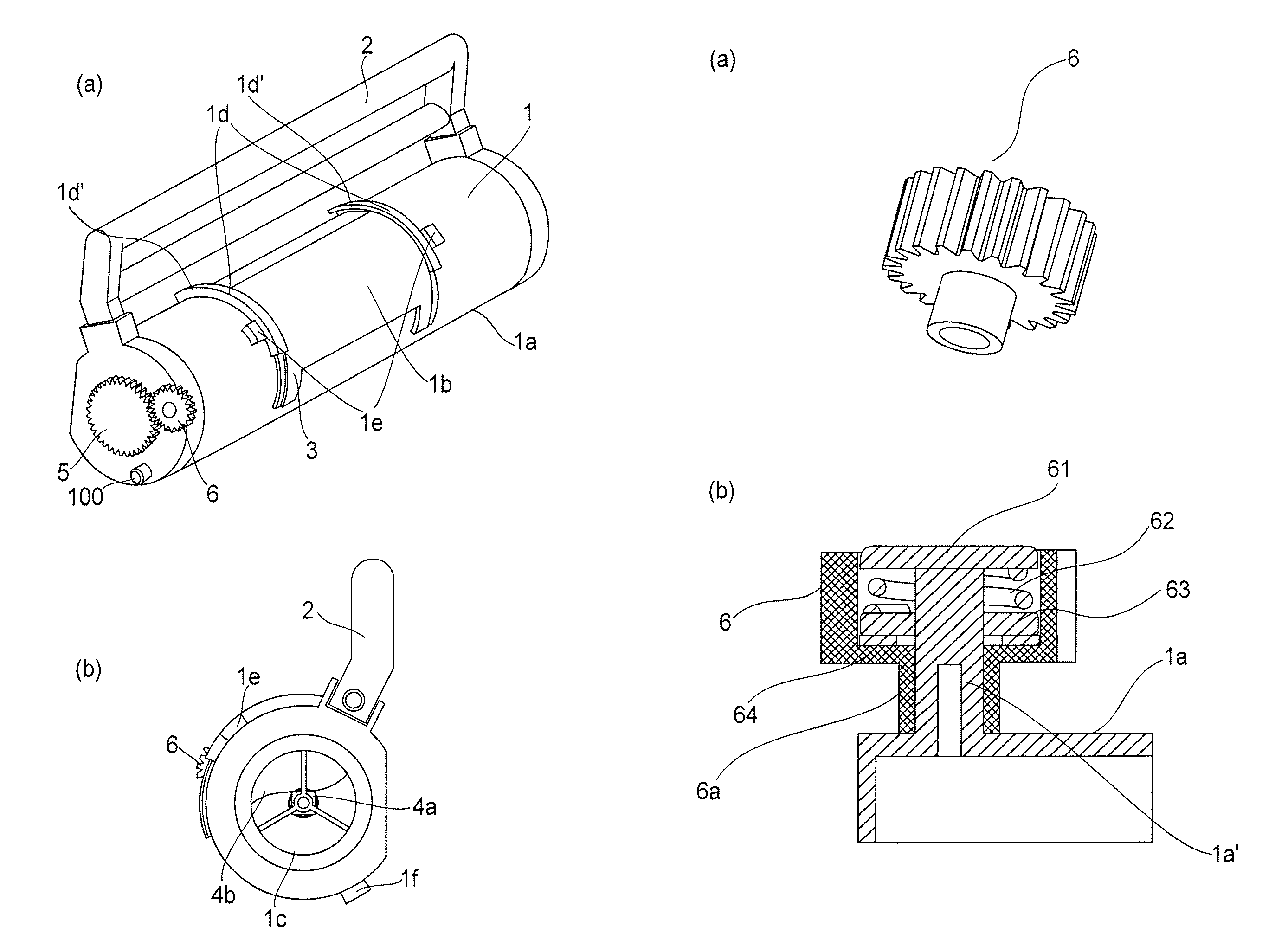
Figure 1 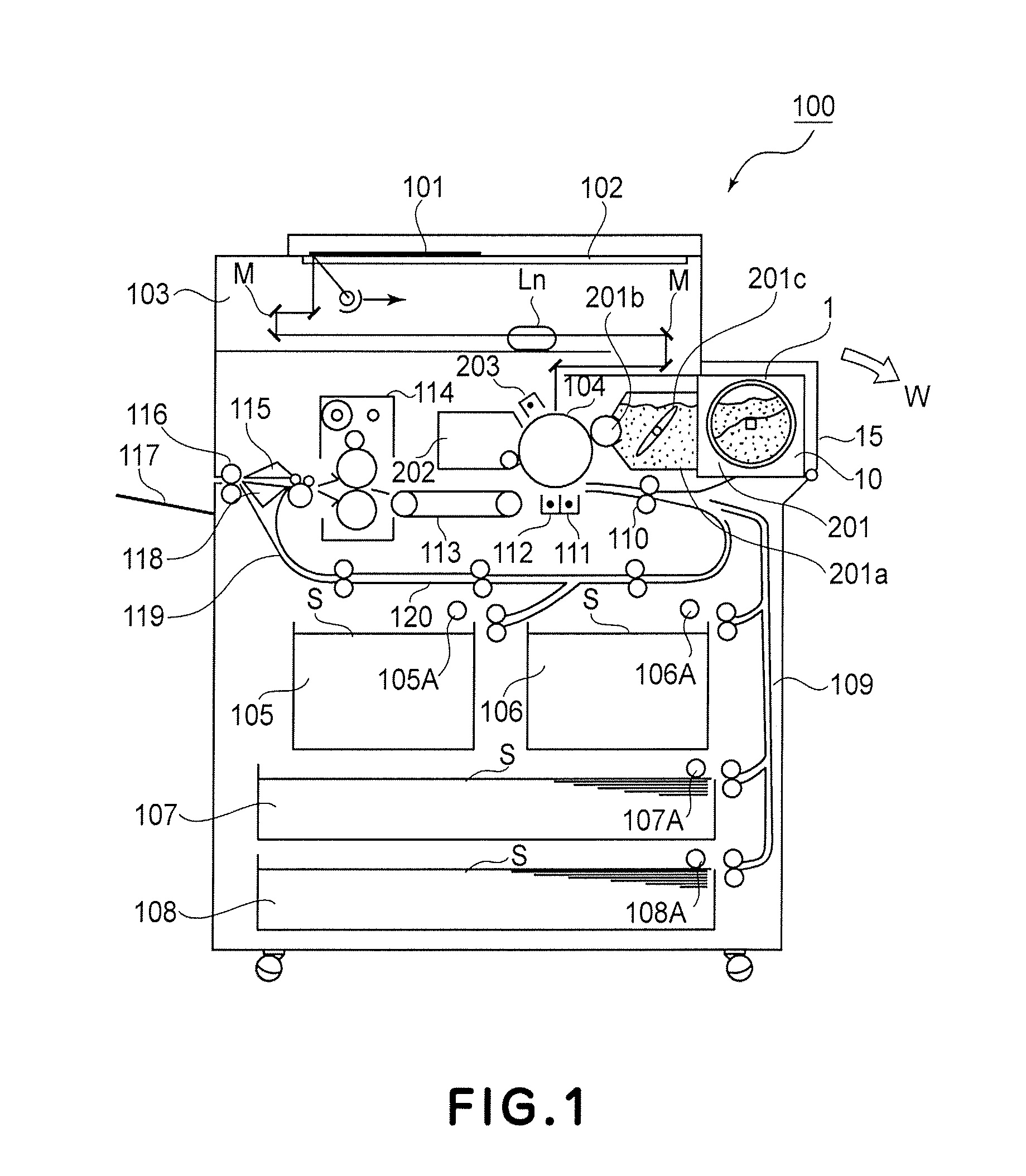
Figure 2 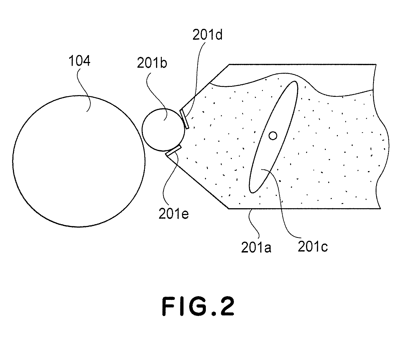
Figure 3
Abstract
Description
TECHNICAL FIELD
[0001] The present invention relates to a developer supply container for supplying the developer and a developer receiving apparatus for receiving the developer from the developer supply container. Such a developer receiving apparatus is usable with a copying machine, a facsimile, a printer or other image forming apparatuses, and an image forming unit detachably mountable to the image forming apparatus.BACKGROUND ART
[0002] Conventionally, toner in the form of fine powder is used as a developer for image formation in the image forming apparatus such as an electrophotographic copying machine, a printer or the like. It is also conventional that toner is supplied from a toner supply container exchangeably set in the image forming apparatus with consumption of the toner in the image forming apparatus.
[0003] Since the toner is very fine powder, the toner may scatter around if the handling in the toner supplying operation is not proper. For this reason, it is proposed and imple...
Examples
embodiment 1
(Image Forming Apparatus)
[0053]A toner supply container of Embodiment 1 (so-called toner cartridge) is loaded into a toner receiving apparatus of an image forming apparatus which is a copying machine of an electrophotographic type in the embodiment.
[0054]FIG. 1 is illustrates such a copying machine.
[0055]In this Figure, designated by 100 is a main assembly of the electrophotographic copying machine. Designated by 101 is an original placed on an original supporting platen glass 102. A light image indicative of image information is projected on an image bearing member in the form of an electrophotographic photosensitive drum 104 through mirrors M and a lens Ln of an optical portion 103. Designated by reference numerals 105-108 are sheet cassettes. A proper sheet is selected from sheet size information of the cassettes 105-108, correspondingly to the sheet size of the original 101 or to the information inputted by the user at the operating portion, and proper sheet is picked up from on...
embodiment 2
[0207]Referring to FIG. 14, a toner supply container 1 according to Embodiment 2 will be described. The basic structures of the container are the same as the embodiment, and therefore, the description of the detail structures thereof is omitted for the sake of simplicity.
[0208]In Embodiment 1, the interrelating portion of the toner supply container uses the opening projection and the sealing projection. In Embodiment 2, a snap fit type engagement is used. In Embodiment 1, the toner supply container is mounted substantially in the direction perpendicular to the longitudinal direction of the toner supply container. In Embodiment 2, however, the toner supply container is mounted to the toner receiving apparatus substantially in the longitudinal direction of the toner supply container.
[0209]This is the main difference of the toner supply container from that of Embodiment 1. In the Figures, the same reference numerals as in Embodiment 1 are assigned to the element having a corresponding ...
embodiment 3
[0259]Referring to FIGS. 22 and 23, Embodiment 3 will be described. The basic structures of this embodiment are the same as Embodiments 1 and 2, and therefore, the detailed description of the common parts are omitted. In the Figures, the same reference numerals as in Embodiments 1 and 2 are assigned to the element having a corresponding function. In FIG. 22, (a) is a perspective view of the entirety of the toner supply container, and (b) is a perspective view of an inner cylinder. In FIG. 23, (a) shows the state when an outer cylinder is at a mount position, and (b) shows the state when the outer cylinder is at a set position, and (c) shows the state when the outer cylinder is at a supplying position.
[0260]In the Embodiments 1 and 2, the container body 1a containing the toner is rotated, but in the present embodiment, a portion not functioning as the toner accommodating portion is rotated.
[0261]As shown in FIG. 22, the toner supply container comprises an inner cylinder 800 containin...