
Construction of coupling exhaust pipes of vehicle
A connection structure and exhaust pipe technology, applied in the direction of flange connection, exhaust device, pipe/pipe joint/pipe fitting, etc., can solve the problems of increased weight and cost, large number of parts, troublesome welding process, etc., to achieve Avoidance of weight, ease of manufacture, effect of reduced quantity
Patent Information
- Authority / Receiving Office
- CN · China
- Patent Type
- Patents(China)
- Current Assignee / Owner
- Publication Date
- 2008-12-31
Smart Images
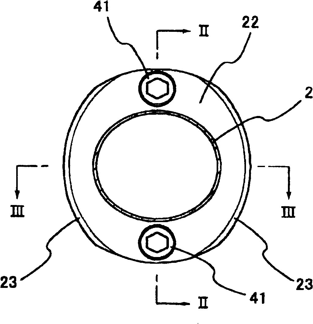
Figure 1 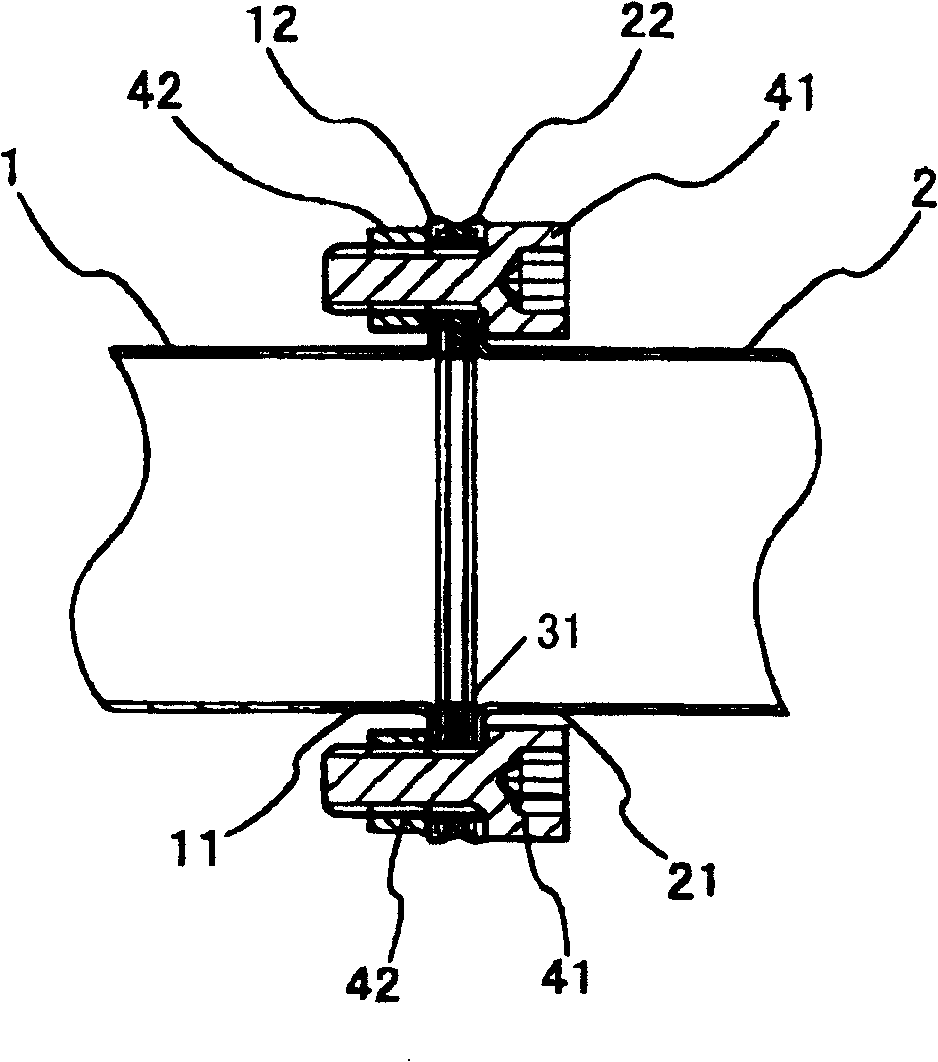
Figure 2 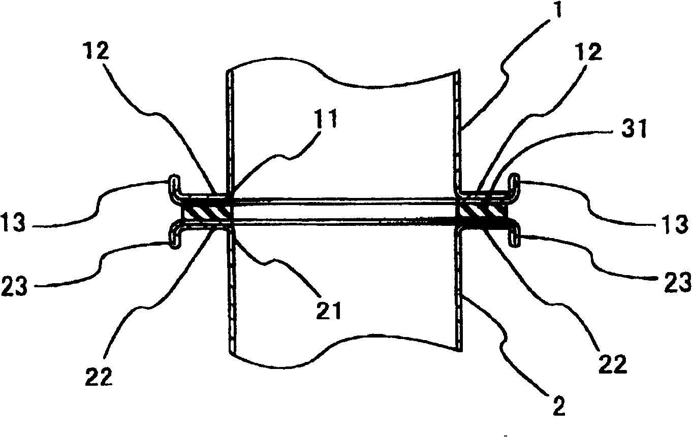
Figure 3
Abstract
Description
Technical field
[0001] The present invention relates to a connection structure of vehicle exhaust pipes, and in particular to a connection structure that can connect exhaust pipes to each other without welding and with a small number of parts. Background technique
[0002] Figures 11 and 12 show an example of a conventional exhaust pipe connection structure. In FIG. 12, the pipe ends of the upstream exhaust pipe 1 and the downstream exhaust pipe 2 are fixed by welding with substantially diamond-shaped (FIG. 11) connecting flanges 61, 62, and bolts 64 and nuts 65 are used. The connecting flanges 61 and 62 are connected via the gasket 63, and the two exhaust pipes 1 and 2 are thus connected together (first prior art example).
[0003] Fig. 13 and Fig. 14 show other examples of the conventional exhaust pipe connection structure. In FIG. 14, the entire circumference of one side of the locking rings 71 and 72 formed in a U-shaped cross-section is welded and fixed to the outer circumfe...
Examples
Embodiment Construction
[0026] (First Embodiment)
[0027] Figure 1 ~ Figure 3 An example of the connection structure of the present invention is shown. figure 1 Is a cross-sectional view of the connected vehicle exhaust pipe, figure 2 , image 3 Respectively along figure 1 The vertical cross-sectional view of the II-II line and the III-III line. in figure 2 , image 3 Among them, the upstream side exhaust pipe 1 and the downstream side exhaust pipe 2 are located such that the opening edges 11 and 21 face each other. The wall thickness of each exhaust pipe 1, 2 is, for example, 1.2 to 1.5 mm, and its opening edges 11, 21 are expanded and formed to bend outward in the radial direction, and then fold inward in the radial direction to form a convex of a predetermined width around the opening. Rim 12,22. The flanges 12 and 22 are provided with a gasket 31 between them, butt against each other, and are symmetrical in the radial direction ( figure 1 ) Combine with bolt 41 and nut 42. The two exhaust pip...