
Hydraulic concrete cutting system
A concrete and hydraulic technology, applied in the field of reinforced concrete cutting equipment for construction, can solve the problems of inability to cut at any angle, single function of the driving mechanism, inconvenient installation, etc., and achieve the effects of reliable output speed, light design, and reliable and fast installation.
Patent Information
- Authority / Receiving Office
- CN · China
- Patent Type
- Applications(China)
- Current Assignee / Owner
- Publication Date
- 2009-07-15
- Estimated Expiration
- Not applicable · inactive patent
Smart Images
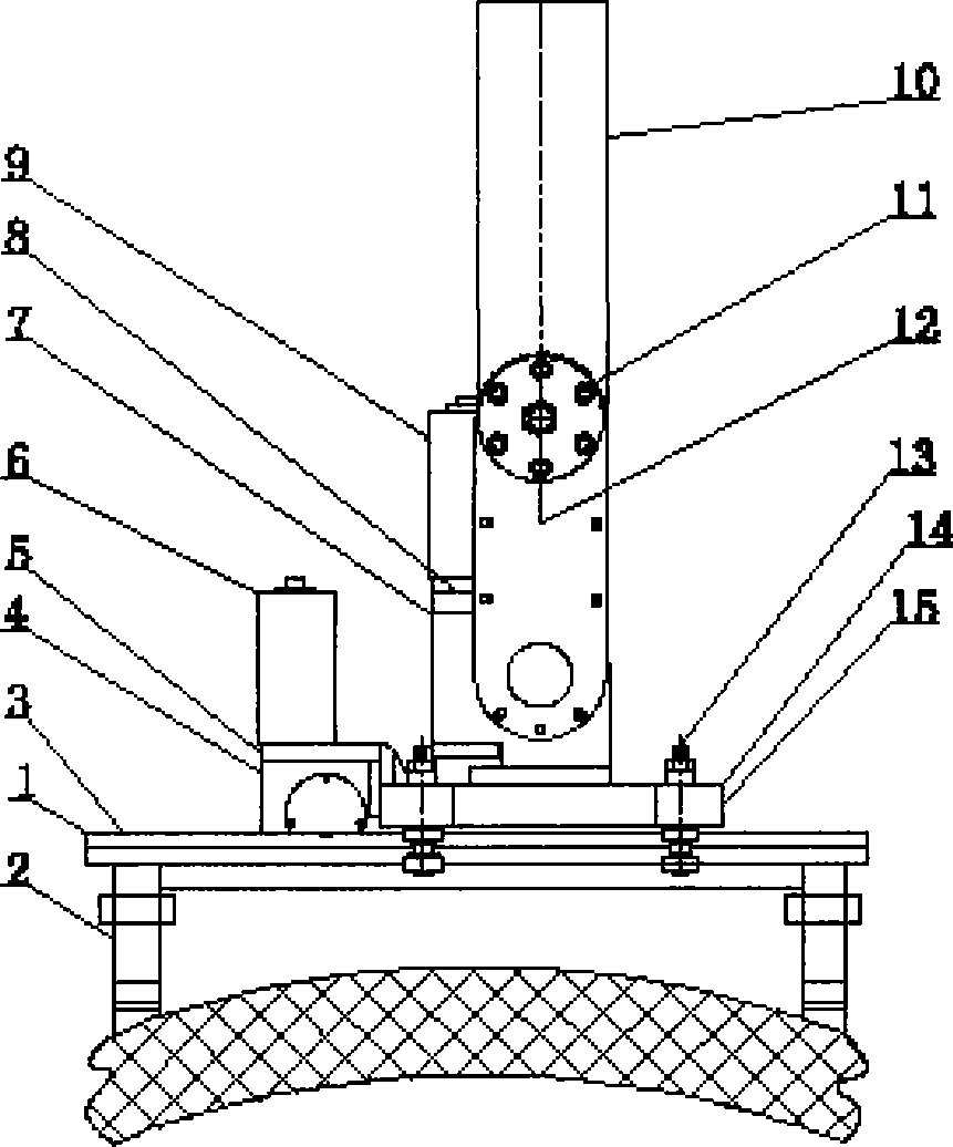
Figure 1 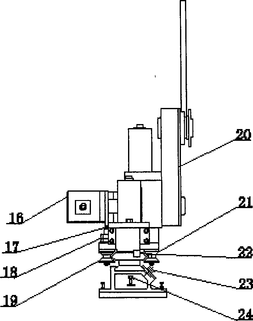
Figure 2 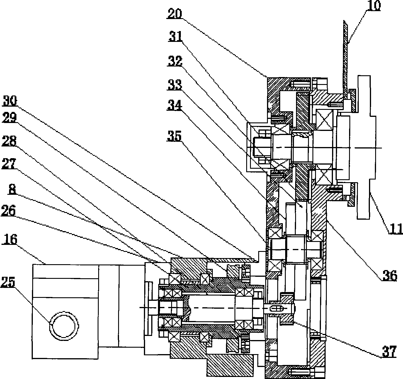
Figure 3
Abstract
Description
technical field
[0001] The invention belongs to reinforced concrete cutting equipment for construction, and in particular relates to a hydraulic hydraulic concrete cutting machine. Background technique
[0002] In recent years, in the industry of chimney reconstruction, construction, bridge, and house reinforcement and reconstruction, some concrete demolition work is often encountered, such as: concrete chimney demolition, partial cast-in-place floor slab, concrete beam, concrete pillar, concrete wall demolition, etc. General workers Use continuous drilling and row holes, or use manual chisel to solve the problem, and finally repair the drilled surface by cement workers. This will affect the local structure of the construction body, and the cycle is long. There are hidden dangers between the repaired surface and the original body. The workload and intensity are high. Moreover, to remove the complex surface of concrete, only manual chiseling can be used. When installing ceme...
Examples
Embodiment Construction
[0036] Example figure 1 , figure 2 As shown in the figure, the equipment is a kind of equipment manufactured comprehensively by mechanical, electrical and hydraulic technologies. It is mainly composed of a hydraulic supply source, an electric control box, a guide rail assembly 1, a knife feed assembly 4, a rotating assembly 7, a deceleration assembly 12, a base assembly 14, and a hydraulic motor 16. The guide rail assembly 1 is fixed on the guide rail support frame 2, the knife feed assembly 4 is fixed on one side of the base assembly 14, the rotation assembly 7 and the deceleration assembly 12 are connected at a vertical angle and fixed above the base assembly 14, and the cutting saw blade is connected on the deceleration assembly 14. On the assembly 12; the hydraulic motor 16 is at one end of the rotating assembly 7 and communicates with the hydraulic supply source through the oil pipe; the electric control box controls the operation of the cutting machine through the cont...