
Numerical control plasma six-shaft five-linkage groove cutting machine
A five-link, plasma technology, used in plasma welding equipment, welding equipment, metal processing equipment, etc., can solve the problems of affecting cutting accuracy and difficult to adjust the cutting torch.
Patent Information
- Authority / Receiving Office
- CN · China
- Patent Type
- Patents(China)
- Current Assignee / Owner
- Publication Date
- 2012-05-23
- Estimated Expiration
- Not applicable · inactive patent
Smart Images
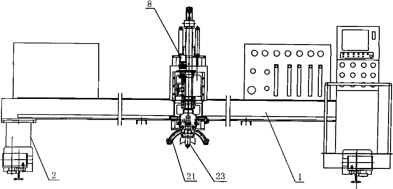
Figure 1 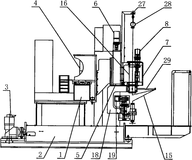
Figure 2 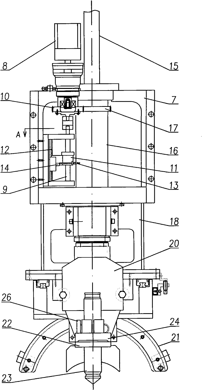
Figure 3
Abstract
Description
1. Technical field
[0001] The invention relates to a numerically controlled plasma bevel cutting machine, in particular to a numerically controlled plasma six-axis five-linkage bevel cutting machine. 2. Background technology
[0002] CNC plasma bevel cutting machine is a multi-axis linkage compound motion cutting machine, which can form V, X, Y-shaped bevels at one time, and complete the bevel processing completed by traditional cutting, milling and other multiple processes at one time, greatly Improve efficiency and save resources. The CNC plasma bevel cutting machine currently in use has been developed to a six-axis five-linkage form with a higher degree of automation. The most fatal defect of plasma cutting is that the arc is not vertical, which causes the cut surface of the cutting workpiece to be inclined. The non-perpendicularity of plasma imported from the United States in the early days was as high as 7 degrees, and the non-perpendicularity of the latest HPR series...
Examples
Embodiment Construction
[0016] Depend on figure 1 , figure 2 with image 3 It can be seen that the CNC plasma six-axis five-link bevel cutting machine of the present invention includes a beam 1, and end frames 2 are installed on both sides of the beam 1, and the two ends of the frame are connected with a longitudinal movement device, and the longitudinal movement device is placed on the track and is driven by a longitudinal movement motor. 3 drive, the lateral moving device is installed on the crossbeam 1 and driven by the lateral moving motor 4, the main engine is connected with the lifting moving device through the bracket 5, and the lifting moving device is driven by the lifting moving motor 6 and connected with the lateral moving device.
[0017] see Figure 4 with Figure 5 , the main engine includes a rotary device, the cabinet 7 of the rotary device is installed on the bracket 5, the rotating motor 8 is installed on the top of the cabinet 7, the output shaft of the rotary motor 8 is connec...