
Starting valve control type lead acid storage battery with pure water chambers
A technology of lead-acid batteries and pure water chambers, which is applied in the direction of lead-acid batteries, lead-acid battery construction, battery pack components, etc. It can solve the problems of poor impact resistance, reduced production efficiency, long running time, etc., and achieves hot melting Good performance and impact resistance, ensuring deep cycle service life and long deep cycle service life
Patent Information
- Authority / Receiving Office
- CN · China
- Current Assignee / Owner
- Publication Date
- 2011-04-06
- Estimated Expiration
- Not applicable · inactive patent
Smart Images
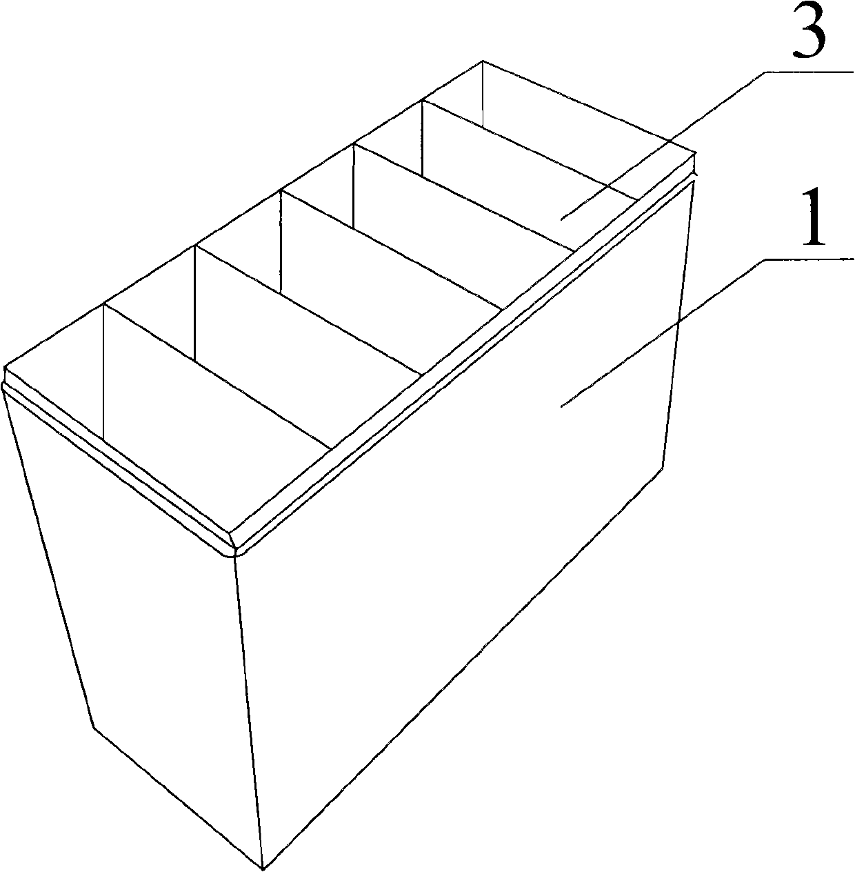
Figure 1 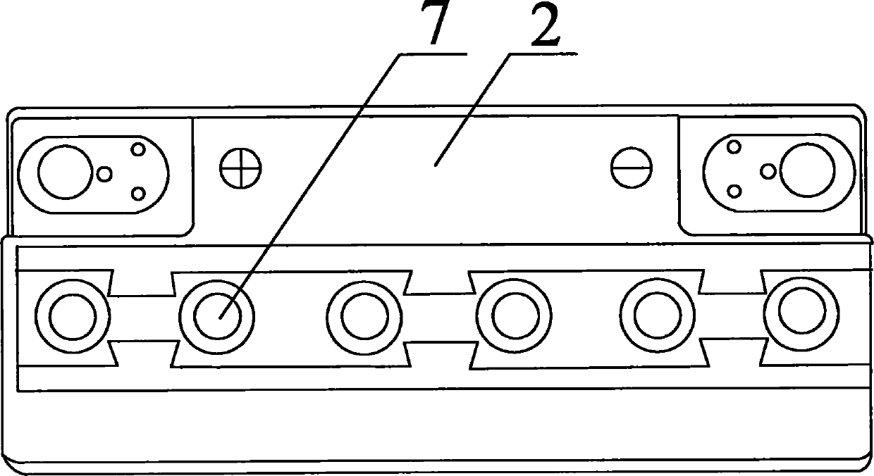
Figure 2 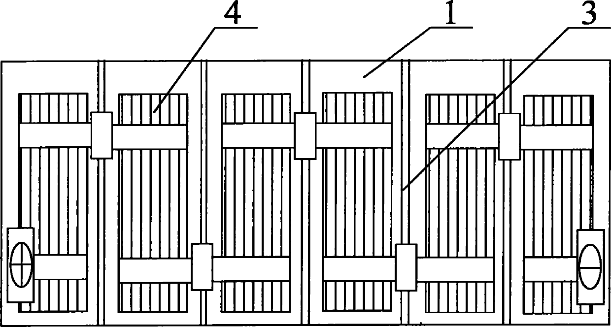
Figure 3
Abstract
Description
technical field
[0001] The invention relates to a lead-acid storage battery for starting, which is mainly used in the fields of automobiles, tractors, construction machinery, etc., and specifically refers to a valve-controlled lead-acid storage battery for starting with a pure water chamber. Background technique
[0002] The structure of lead-acid storage battery mainly contains positive (negative) pole plate, dividing plate, electrolyte, battery tank, connecting bar and positive and negative terminal etc. to form, and positive (negative) pole plate is that grid among the present invention is coated with lead paste constitute. A lead-acid battery is a device that converts chemical energy into electrical energy and belongs to the DC power supply.
[0003] At present, the manufacturing process of valve-regulated lead-acid batteries (abbreviated as VRLA) with ABS plastic battery tank covers is roughly as follows:
[0004] Alloy Configuration→Grid Manufacturing→Mechanical Coat...
Examples
Embodiment
[0038] Such as Figure 1-8 As shown, the valve-regulated lead-acid battery with the pure water chamber 5 is mainly composed of a battery tank 1 divided into twelve cells by an intermediate wall 3, and a battery cover 2 matching the battery tank 1. The battery tank 1, the middle wall 3 and the battery cover 2 are all made of PP plastic material.
[0039] Such as Figure 4 As shown, the single-cell battery tank 1 is distributed in two rows, one of which is the electrode group chamber 12, and the electrode group 4 is placed in the electrode group chamber 12 and filled with electrolyte, and the other row is the pure water chamber 5 Each pole group 4 corresponds to a pure water chamber 5, and a communication conduit 6 is provided between the pole group 4 and the corresponding pure water chamber 5, and the communication conduit 6 extends to the bottom of the pure water chamber 5. Such as Figure 8 As shown, in the lower section of the intermediate wall 3 between the pole group ch...