
Claw beam lifting mechanism for forging manipulator
A technology of forging operation and lifting mechanism, which is applied in the direction of forging/pressing/hammering machinery, manufacturing tools, forging/pressing/hammer devices, etc. It can solve the problems of difficult installation and maintenance, complex structure of synchronous connecting rod pin assembly, and difficulty in ensuring forgings Accuracy and other issues, to achieve the effect of low manufacturing cost, convenient installation, adjustment and maintenance, and simple structure
Patent Information
- Authority / Receiving Office
- CN · China
- Patent Type
- Patents(China)
- Current Assignee / Owner
- Publication Date
- 2012-09-05
- Estimated Expiration
- Not applicable · inactive patent
Smart Images
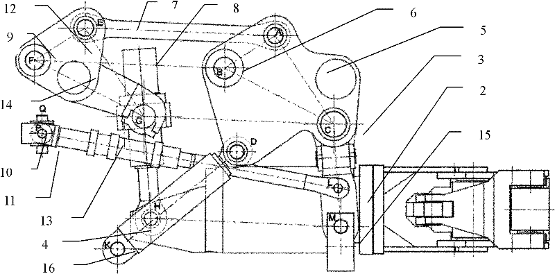
Figure 1 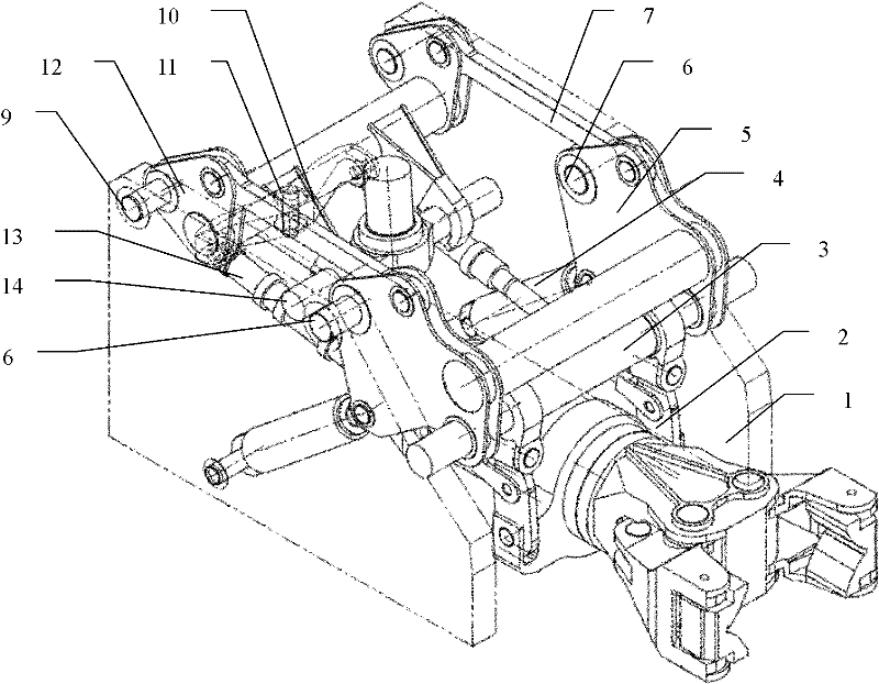
Figure 2 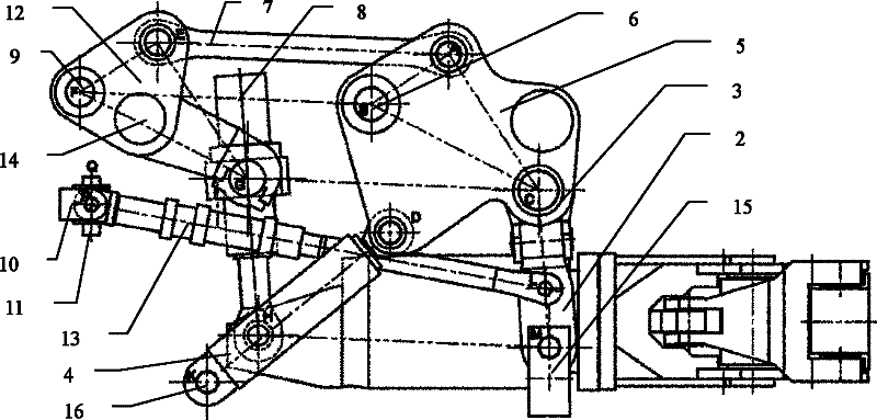
Figure 3
Abstract
Description
Technical field:
[0001] The invention relates to a mechanism used in the technical field of forging processing equipment for manipulating the tong rod in the forging operation machine to perform forging actions such as lifting and tilting. Realize the mechanism for manipulating the tong rod to lift. Background technique:
[0002] The forging manipulator is one of the basic tools for large-scale forging press processing, and it is a major equipment to realize the mechanization of forging production, and it is used in conjunction with the press. The current forging manipulators include wire rope hanging type, multi-rod mechanism combined type, etc. The wire rope hanging type forging manipulator has a small operating capacity and is used for small-scale forging, while the multi-bar mechanism combined forging manipulator has a large operating capacity and is used for large-scale forging. The forging manipulator is not only used to clamp forgings and billets for forging and pre...
Examples
Embodiment Construction
[0012] With reference to the accompanying drawings, the tong rod lifting mechanism of the forging manipulator is mainly composed of a front lifting component, a rear lifting component, a synchronous connecting rod 7, a lifting cylinder 4, a pitching cylinder 8 and a buffer component. The rear fixed shaft 9 in the lifting part and the lower end of the lifting cylinder 4 are hingedly connected with the cart frame 1 respectively, and the synchronous connecting rod 7 adopts the upper mode, that is, the working range of the synchronous connecting rod 7 is always within the lifting and tilting mechanism of the clamp rod 15 In the upper part of the line connected with the 6 hinge points of the front fixed shaft of the cart frame 1 and the 9 hinge points of the rear fixed shaft, the front ends of the two buffer cylinders 13 are respectively hinged with the two front lifting links 2, and the rear ends are respectively hinged on the compensation beam 10 At both ends, the middle part of t...