
ironing device
一种熨烫装置、把手的技术,应用在洗涤装置、手熨斗、纺织品和造纸等方向,能够解决施加不实用、不允许实用方式控制其它功能等问题
Patent Information
- Authority / Receiving Office
- CN · China
- Patent Type
- Applications(China)
- Current Assignee / Owner
- Publication Date
- 2011-12-28
- Estimated Expiration
- Not applicable · inactive patent
Smart Images
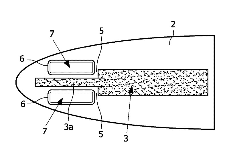
Figure 1 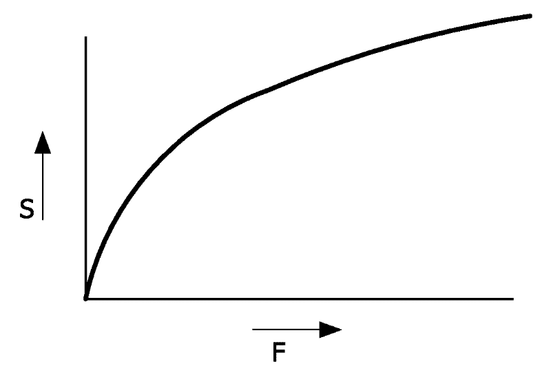
Figure 2 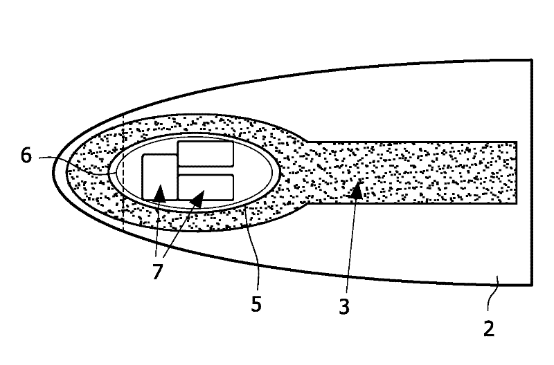
Figure 3
Abstract
Description
Technical field
[0001] The invention relates to an ironing device. More specifically, the present invention relates to the arrangement and structural design of the handle of an ironing device. Background technique
[0002] Several ironing devices have been proposed in the prior art. French patent FR 602 293 proposes an ironing device with a pivotally connected handle, and when an operating force is applied to the handle, the handle opens the valve to generate steam. After the operating force is removed, the valve is closed and steam generation is stopped.
[0003] The disadvantage of this ironing device is that the pivot of the handle of this device is positioned at the rear end of the handle, which requires the user to apply an impractical forward tilt force to the handle to release steam.
[0004] Another disadvantage is that the ironing device in this document does not allow to control other functions, such as spray function, steam spray function, fixed dose and / or measurement ...
Examples
Embodiment Construction
[0022] figure 1 A side view of the ironing device 1 is depicted. The ironing device 1 includes a base 2 and a handle 3. An ironing bottom 15 is arranged below the base 2, which may be provided with steam and / or water holes 16. A reservoir 13 for water is arranged in the base 2 or the handle 3. Even though figure 1 In this case, the reservoir is arranged in the ironing device. Alternatively, the reservoir may be a separate or remote reservoir, for example connected to the ironing device via a water or steam transport line. During the use of the ironing device 1, steam may be generated when ironing clothes and released or discharged through the holes 16.
[0023] in figure 1 Here, the handle 3 is pivotally connected to the base 2 by a pivot 8. The handle 3 is also provided with a cutout or recess 5 in which the console 6 is placed. On the console 6, operation buttons, controls 7 and / or displays can be arranged. The lower side of the console 6 is installed on the base 2 of the ...