
Outer skin fastening device for small optical cable
A fastening device and small-scale technology, applied in the direction of fiber mechanical structure, etc., can solve the problems of large push-in force, insufficient fastening force, failure to achieve the purpose of fastening, etc., and achieve large pull-off force and low construction strength. , compact structure
Patent Information
- Authority / Receiving Office
- CN · China
- Patent Type
- Patents(China)
- Current Assignee / Owner
- Publication Date
- 2014-03-05
Smart Images
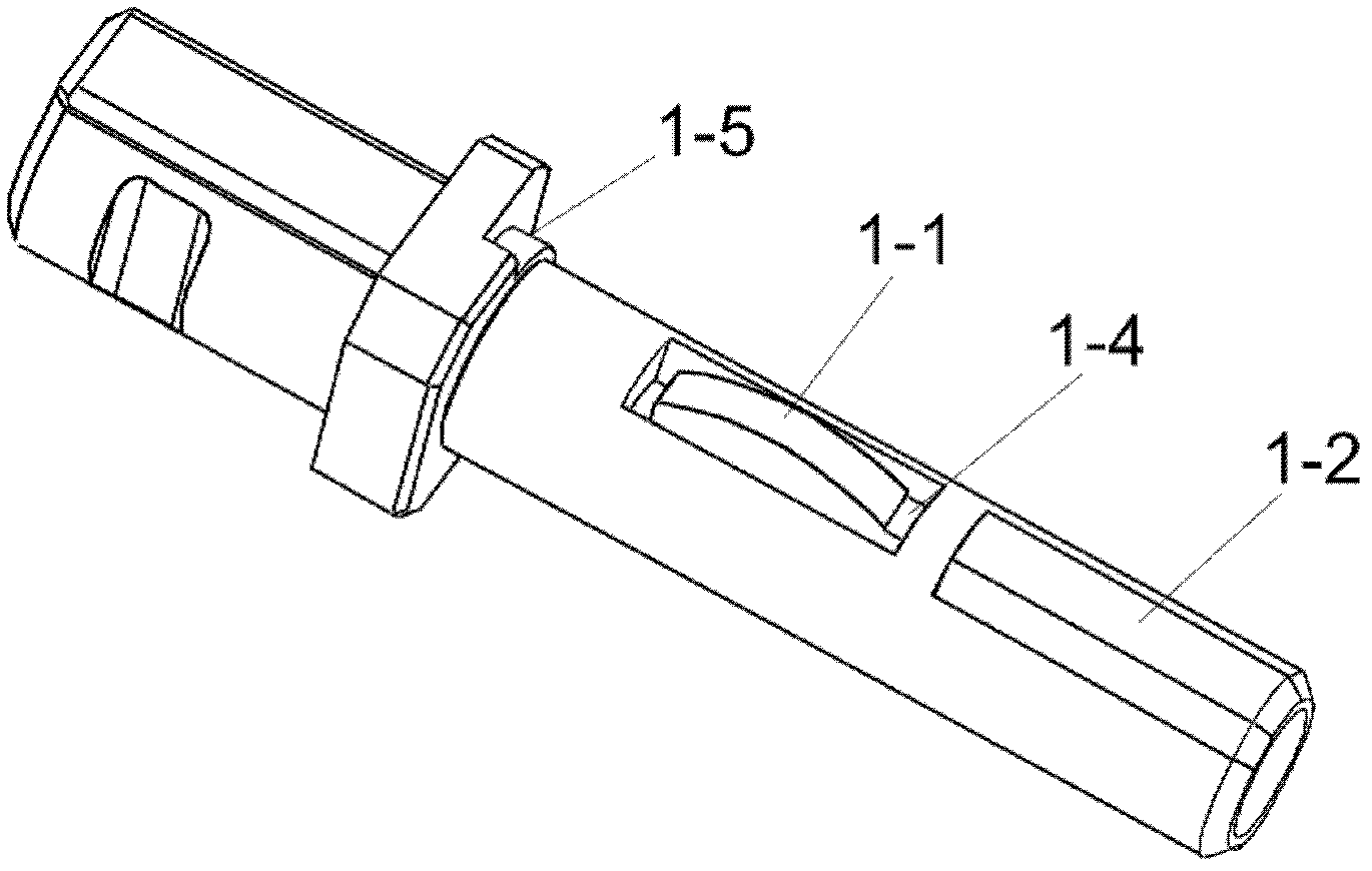
Figure 1 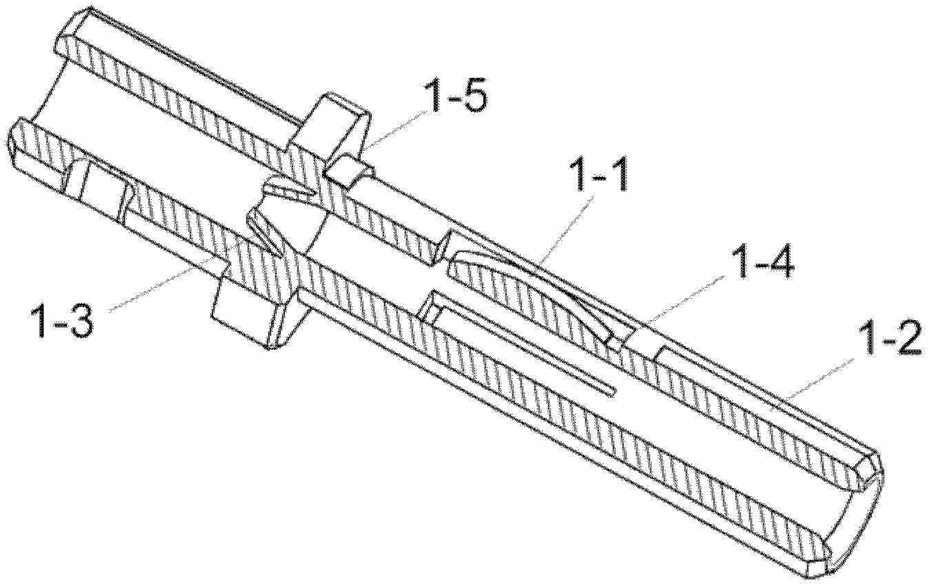
Figure 2 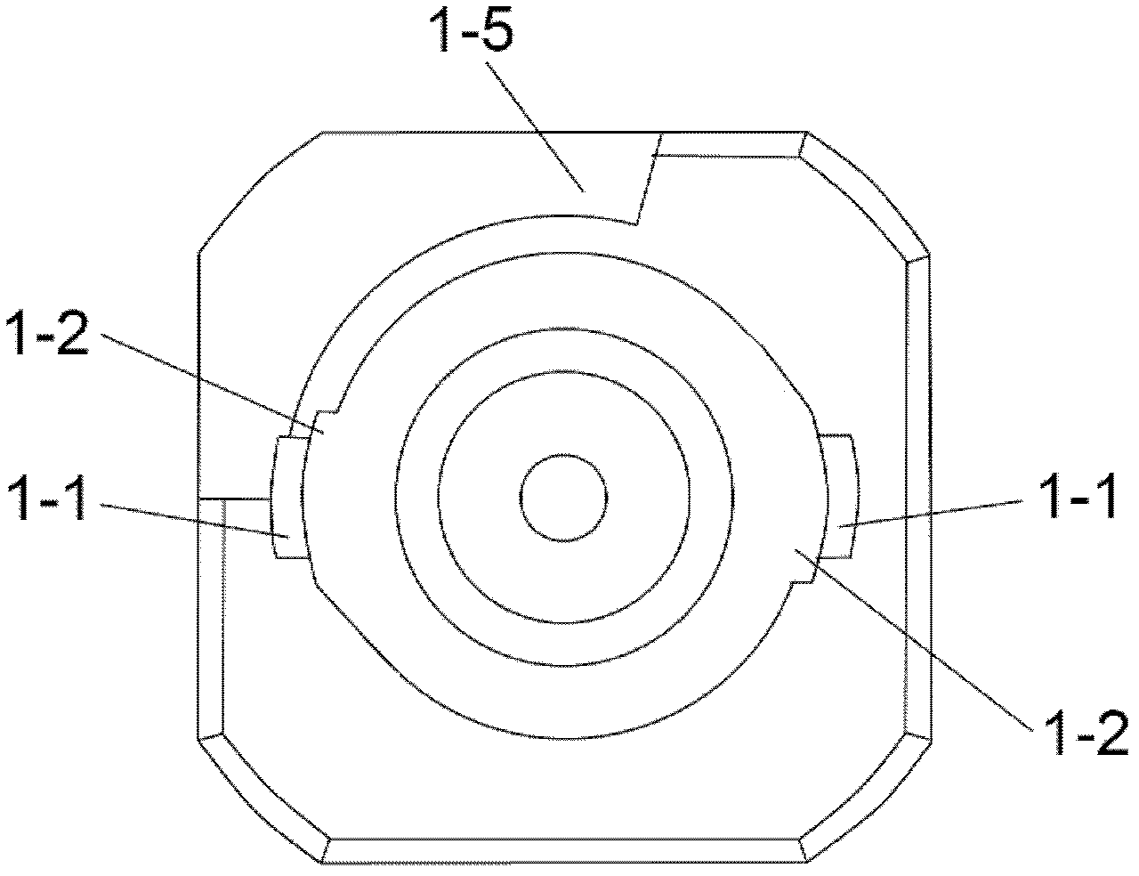
Figure 3
Abstract
Description
technical field
[0001] The invention relates to a fastening device for a small-sized optical cable sheath, in particular to a fastening device for an optical cable. Background technique
[0002] As the coverage density of FTTH fiber-to-the-home is getting higher and higher, when the optical fiber is connected in the corridor distribution cabinet, distribution box, and outdoor cabinet, the specification of the fastened optical cable is getting smaller and smaller, and the outer sheath of the optical cable is between 0.25mm and 1.2mm. It is defined as a small-sized optical cable. There is no good method for fastening the sheath of these small-sized optical cables. At present, there are two main methods for fastening the outer sheath of the optical cable:
[0003] The first is to arrange arc grooves at the end of the V-shaped groove and the end of the gland respectively. When working, the optical fiber in the V-shaped groove is compressed while the space of the arc groove is re...
Examples
Embodiment Construction
[0020] The present invention will be described in detail below in conjunction with the accompanying drawings.
[0021] As shown in Figure 1 and 2:
[0022] It includes a tail handle 1 and a push tube 2; a pair of press pliers 1-1 are symmetrically arranged in the middle of the tail handle 1, and two arc cutting tables 1-2 are arranged in the same angular direction of the press pliers 1-1, as Figure 1a As shown, the arc cutting table 1-2 and the press pliers 1-1 are on the same radial direction, one side of the arc cutting table 1-2 is smoothly connected with the tail shank, and the radius of the other side gradually increases to form a circle with the tail shank. Steps, a guide cone ring 1-3 is set in the front hole of the tail handle; an arc cut groove 2-1 matching the arc cut table 1-2 on the tail handle 1 is arranged in the push tube 2; the fastening device mainly Press down the clamp 1-1 on the tail handle 1 through the two-step operation of pushing and rotating the push ...