
Changeable retractor device for railroad bridge
A telescopic device and bridge technology, applied in bridges, bridge construction, bridge parts, etc., can solve the problems of damaged waterproof belts, difficult installation, inability to replace, etc., and achieve large clamping force reserve, protection performance guarantee, and good waterproof performance. Effect
Patent Information
- Authority / Receiving Office
- CN · China
- Patent Type
- Applications(China)
- Current Assignee / Owner
- Publication Date
- 2012-11-21
- Estimated Expiration
- Not applicable · inactive patent
Smart Images
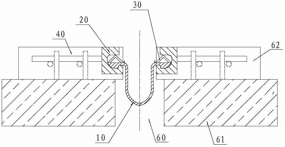
Figure 1 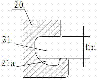
Figure 2 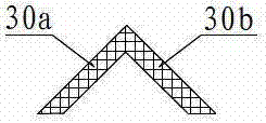
Figure 3
Abstract
Description
Technical field
[0001] The invention relates to a railway bridge, in particular to a replaceable expansion device for expansion joints between beam bodies of railway bridges. Background technique
[0002] Railway is the main artery of the national economy, and railway transportation has always served the society and the people. With the rapid development of the national economy, the state has given railway transportation more arduous tasks and higher standards. So far, China's existing railway operating mileage has reached 91,000 kilometers, and there are about 50,000 bridges over 4,000 kilometers. In newly-built railways, the total length of bridges accounts for an increasing proportion of the total line length. For example, the total length of the Beijing-Tianjin intercity railway bridge accounts for about 88% of the total line length, and the total length of the Beijing-Shanghai high-speed railway bridge accounts for about 81% of the total line length. Except for a small nu...
Examples
Embodiment Construction
[0023] The present invention will be further described below in conjunction with the drawings and embodiments.
[0024] Reference figure 1 , The replaceable telescopic device of the railway bridge of the present invention includes a pair of connecting strips 20 fixed on the two side walls of the expansion joint 60 by an anchoring member 40, and a waterproof belt 10 connected with the connecting strips 20 on both sides. 20 has an anchor groove 21 extending in the full length direction. Reference figure 1 , figure 2 with Figure 4 The two sides of the waterproof belt 10 have downwardly protruding anchor fixing bosses 11, and the cross-sectional shape of the anchor fixing boss 11 matches the cross-sectional shape of the groove 21 a under the anchor groove 21. The two sides of the waterproof tape 10 are pulled into the anchor groove 21 from the longitudinal end of the connecting strip 20, and the locking strip 30 is pressed into the space between the upper surface of the waterproof ...