

Four-wheel draw-bar box
A trolley case, wheeled technology, applied to luggage, clothing, accessories, etc., can solve the problems of increased fatigue, easy hand fatigue, and the trolley case cannot be placed vertically, achieving less fatigue, easy dragging, and simple structure. Effect
Patent Information
- Authority / Receiving Office
- CN · China
- Current Assignee / Owner
- Publication Date
- 2013-09-18
- Estimated Expiration
- Not applicable · inactive patent
Smart Images
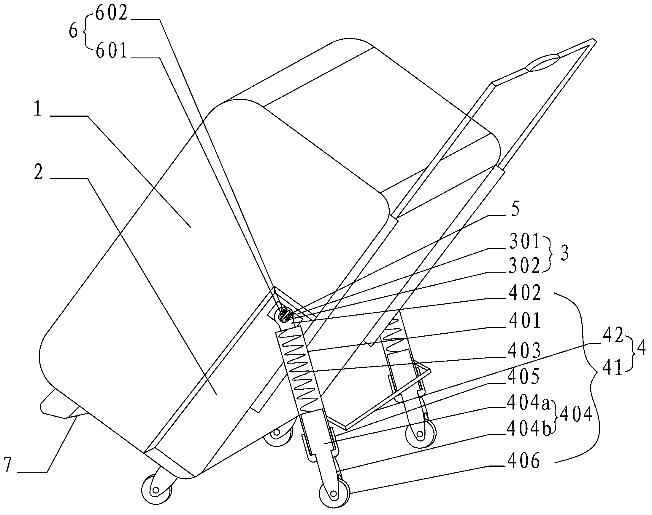
Figure 1 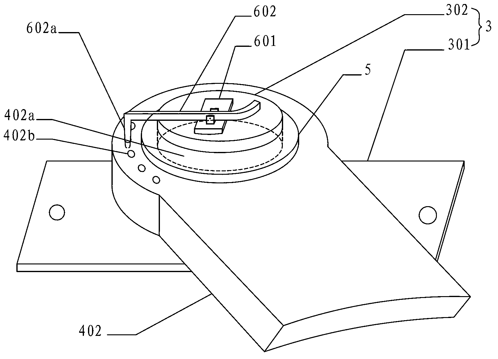
Figure 2
Abstract
Description
technical field
[0001] The invention relates to a four-wheel trolley case. technical background
[0002] Most of the trolley cases on the market today are of two-wheel structure, and the four-wheel trolley case is only to solve the problem that the trolley case cannot be placed vertically. The resistance generated by the trolley case also needs to bear part of the gravity of the trolley case, so when there is a lot of luggage, dragging the trolley case will make the hands more tired, and if the ground is uneven, frequent vibrations when dragging the trolley case , exacerbated the degree of fatigue. Contents of the invention
[0003] The technical problem to be solved by the present invention is to provide a four-wheel trolley case that is easy to drag, absorbs vibrations, and is not easy to be tired.
[0004] In order to solve the problems of the technologies described above, the present invention adopts the following technical solutions:
[0005] A four-wheeled trolley...
Examples
Embodiment Construction
[0018] The specific implementation manners of the present invention will be described in detail below in conjunction with the accompanying drawings.
[0019] Such as figure 1 and figure 2 As shown, a four-wheeled trolley case includes a trolley case body 1, a cavity 2 is provided on both sides of the trolley case body 1, and the inner wall of the cavity 2 is fixed to a shaft block 3, and the shaft block 3 includes a steel sheet part 301 and shaft part 302, the shaft part 302 is movably connected to the wheeled elastic leg 4, the outer side of the wheeled elastic leg 4 is provided with a limit sleeve 5 fixed on the shaft part 302, and the end surface of the shaft part 302 Elastic lever 6 is provided on. The wheeled elastic support leg 4 includes two single legs 41 arranged in parallel, and the two single legs 41 are connected by a cross bar 42 . The single leg 41 includes a casing 401, which is a cylindrical aluminum alloy tube, and an external thread 401a is provided on th...