

Portable hydraulic pipe bending machine
A pipe bender, a portable technology, applied in the field of portable hydraulic pipe benders, can solve problems such as tube bundle bending that cannot be solved, and achieve the effect of solving tube bundle bending problems, large bending moment, and small size
Patent Information
- Authority / Receiving Office
- CN · China
- Patent Type
- Applications(China)
- Current Assignee / Owner
- Publication Date
- 2013-09-25
Smart Images

Figure 1 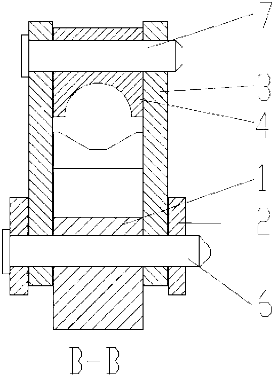
Figure 2
Abstract
Description
technical field
[0001] The invention relates to a portable hydraulic pipe bending machine with compact structure, large bending moment and limited operating space, which belongs to the technical field of pipe bending machines. Background technique
[0002] At present, there are a large number of highly automated and high-precision pipe bending equipment on the market. The size of such equipment is usually large, with a length, width and height of several meters, and only straight pipes can be installed on the pipe bending equipment alone for bending. . For on-site bent pipes with limited operating space, such as but not limited to, each thick-walled straight pipe in the bent pipe bundle is parallel to each other, and the distance between them is only 3 to 5 times the outer diameter of the straight pipe. A bend with a bending radius of about 5 to 10 times the outer diameter of the pipe, and to ensure that the bent pipe and the pipe bender do not collide with the surrounding ...
Examples
Embodiment Construction
[0017] The technical solution of the present invention will be described in detail below in conjunction with the accompanying drawings and specific embodiments. The following examples are used to illustrate the present invention, but are not intended to limit the scope of the present invention.
[0018] Such as figure 1 , figure 2 As shown, the portable hydraulic pipe bender of this embodiment is mainly divided into the following parts:
[0019] Membrane (1), moving beam (2), tie rod (3), briquetting block (4), piston (5), pin shaft (6), small pin (7), high-pressure hose (8), manual hydraulic pump (9).
[0020] The connection relationship of each part is as follows: the tire membrane (1) is hinged with the tie rod (3) and the moving beam (2) through the pin shaft (6); ) is hinged; the piston (5) is located in the oil cylinder inside the membrane (1).
[0021] The characteristics of each part are as follows:
[0022] The membrane (1) is a C-shaped plane symmetrical struc...