
Winding device
A winding device and wire trough technology, which is used in transportation and packaging, transportation of filamentous materials, and thin material processing, etc., can solve the problems of uncompact winding, prone to gaps and overlaps in winding, and uneven wire ends. , to achieve the effect of compact winding
Patent Information
- Authority / Receiving Office
- CN · China
- Patent Type
- Applications(China)
- Current Assignee / Owner
- Publication Date
- 2014-02-19
Smart Images
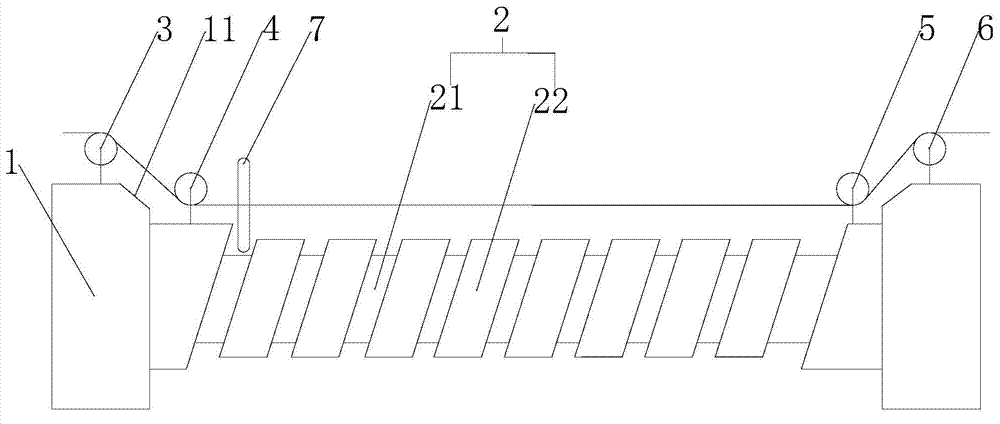
Figure 1
Abstract
Description
technical field
[0001] The invention relates to a winding device. Background technique
[0002] The winding device is used to wind multiple sets of wires. Due to the thickness of the wires, the wires cannot completely coincide with the cross-section of the rotating shaft during the winding process, and the winding will not be compact during the winding process. There are gaps and overlaps between them. At the same time, the angle and strength of the winding are not uniform, and the thread ends are uneven. Contents of the invention
[0003] In order to solve the technical problems existing in the background technology, the present invention proposes a winding device, which improves the winding device. The structure is simple, and the winding can be compact and smooth.
[0004] A winding device proposed by the present invention includes a rotating shaft, the two ends of the rotating shaft are mounting seats, a number of wire grooves are arranged on the rotating shaft, the ...
Examples
Embodiment Construction
[0009] Such as figure 1 as shown, figure 1 It is a structural schematic diagram of a winding device proposed by the present invention.
[0010] refer to figure 1 , a winding device proposed by the present invention, including a rotating shaft 2, the two ends of the rotating shaft 2 are mounting seats 1, a number of wire grooves 21 are arranged on the rotating shaft 2, the two sides of the wire groove 21 are ridges 22, and the sides of the wire groove 21 The edge and the center line of the rotating shaft 2 are in a non-perpendicular relationship, and the two ends of the rotating shaft 2 are provided with end plates near the mounting seat 1, and the mounting seat 1 and the end plates at both ends of the rotating shaft 2 are sequentially provided with a first pulley 3 and a second pulley 4 , the third pulley 5, the fourth pulley 6, the traction line enters from the first pulley 3 and walks around the second pulley 4, the third pulley 5 is pulled out from the fourth pulley 6, an...