
Fixing clamp used for welding of buttons on button board and welding method
A technology for fixing fixtures and key boards, applied in electrical components, electrical switches, circuits, etc., can solve the problems of low welding accuracy, interference, and keys are prone to skew, avoid sliding or offset, improve the quality of finished products, and improve welding. The effect of precision
Patent Information
- Authority / Receiving Office
- CN · China
- Current Assignee / Owner
- Publication Date
- 2014-06-11
Smart Images
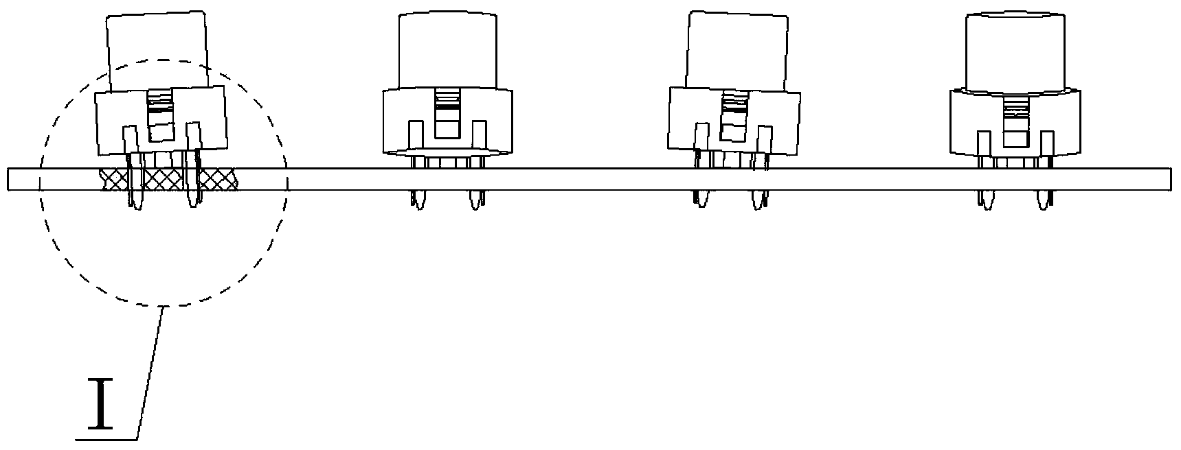
Figure 1 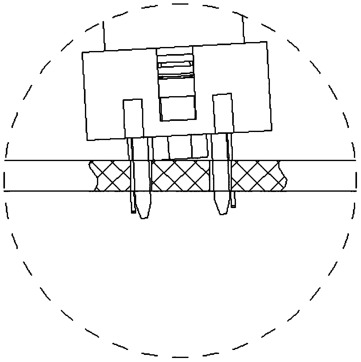
Figure 2 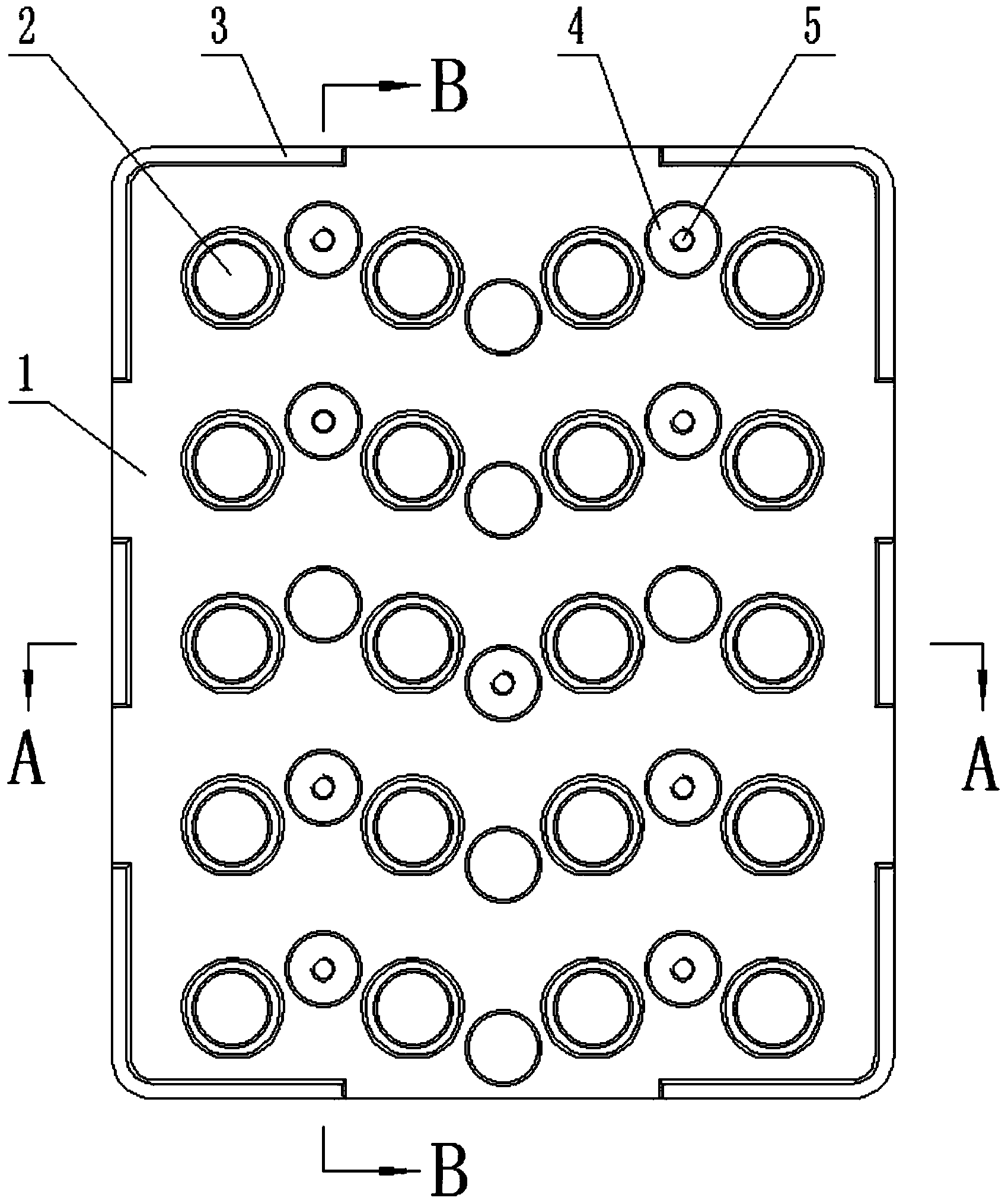
Figure 3
Abstract
Description
technical field
[0001] The invention relates to the technical field of component welding on a printed circuit board, in particular to a fixing fixture and a welding method for welding keys on a key board. Background technique
[0002] At present, when it is necessary to solder and install buttons on the button circuit board, it is generally necessary to design reserved via holes (pin holes) when printing the button board, then insert the pins of the buttons through the via holes, and finally complete the soldering of the pins Button installation. However, due to the large number of button pins (generally 4 to 8), it is necessary to insert all the pins into the via holes on the circuit board when installing and soldering the keys. The size of the via hole should be at least 0.4mm larger than the pin size. . And after inserting the pins of the button into the via hole of the circuit board, the limit is fixed by the limit mechanism such as the welding limit column at the bott...
Examples
Embodiment 1
[0050] Example 1: When it is necessary to weld 20 keys 7 distributed in 4×5 on the five-slice key board, take the pin 9 of the key 7 and insert it into the center of the via hole to compress the height after welding, the length of the key board 10 and the five-screw key The width of plate, remove seat plate 1 height with the distance greater than button 7 height 1mm, but the length and width of seat plate 1 with the distance of 5mm more than key plate 10 length and five spell key plate width respectively. The extra 5mm side of length and width divides the two sides equally, leaving a 0.1mm installation gap for each, and then designing a limit side 3 with a width of 2.4mm and a height 0.5mm higher than the thickness of the keypad 10, to limit the placement range of the keypad 10, The key board 10 needs to print a metal edge with a width of about 2 mm on the side board and the mounting hole 5 to prevent the key board 10 from being damaged by static electricity.
[0051] When in ...
Embodiment 2
[0052] Example 2: When it is necessary to weld 40 keys 7 distributed in 8×5 on the five-slice key board, take the pin 9 of the key 7 and insert it into the center of the via hole to compress the height after welding, the length of the key board 10 and the five-screw key The width of plate, remove seat plate 1 height with the distance greater than button 7 height 1.5mm, but the length and width of seat plate 1 with respectively more than 5mm of key plate 10 lengths and five spell key plate widths. The extra 5mm side of length and width divides the two sides equally, leaving a 0.1mm installation gap for each, and then designing a limit side 3 with a width of 2.4mm and a height 0.5mm higher than the thickness of the keypad 10, to limit the placement range of the keypad 10, The key board 10 needs to print a metal edge with a width of about 2 mm on the side board and the mounting hole 5 to prevent the key board 10 from being damaged by static electricity.
[0053] When in use, firs...
Embodiment 3
[0054] Example 3: When it is necessary to weld 30 keys 7 distributed in 6×5 on the five-slice key board, take the pin 9 of the key 7 and insert it into the center of the via hole to compress the height after welding, the length of the key board 10 and the five-screw key The width of plate, go seat plate 1 height with the distance greater than button 7 height 2mm, but the length and width of seat plate 1 with the distance of 5mm more than key plate 10 length and five spell key plate width respectively. The extra 5mm side of length and width divides the two sides equally, leaving a 0.1mm installation gap for each, and then designing a limit side 3 with a width of 2.4mm and a height 0.5mm higher than the thickness of the keypad 10, to limit the placement range of the keypad 10, The key board 10 needs to print a metal edge with a width of about 2 mm on the side board and the mounting hole 5 to prevent the key board 10 from being damaged by static electricity.
[0055] When in use,...